


2101510 Rev. AG
Page 3–11
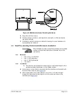
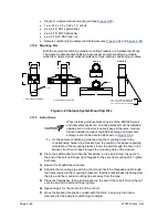
6)
Position the enclosure on the stand, centering the stand underneath or offset as
desired and tighten all bolts.
7)
Foot plate mounting holes are pre-drilled for mounting to a pad. Hardware is to
be supplied by the customer.
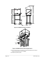
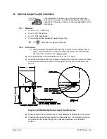
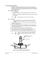
3.7 Large Pipe-Mounted Environmental Enclosure Mounting Kit
If the installation includes a pipe-mounted environmental
enclosure, follow these instructions as well as the optional
support leg instructions, if applicable. Otherwise, continue to
the next applicable set of instructions.
3.7.1
Materials
•
4 ea. ½” -13 x 1 ¼ SST bolt
•
4 ea. ½” SST flat washer
•
4 ea. ½” SST split washer
•
2 ea. 2 ½” x ¼” 43” steel angle iron
May be used in conjunction with optional support leg kit. See
Optional Support Leg Kit Installation
3.7.2
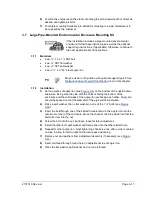
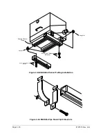
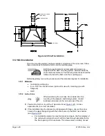
Installation
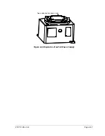
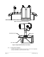
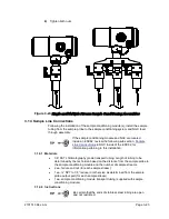
1)
Set two pieces of angle iron (see
) on the bottom of the upside down
enclosure, being sure the side with the holes is facing the bottom of the
enclosure and the solid sides of the angle iron are facing each other. Angle iron
should be spaced so that the diameter of the pipe will fit in-between.
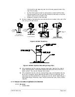
2)
Place a split washer, then a flat washer on one of the 1 ¼” bolts (see
3)
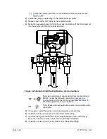
Insert the bolt through one of the slotted holes located in the angle iron into the
outermost corner of the enclosure. Move the channel nut into position so that the
bolt will screw into the nut.
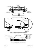
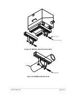
4)
Screw the bolt into the nut, but leave loose for later adjustment.
5)
Install the other bolt, split washer and flat washer into the other slotted hole.
6)
Repeat for other angle iron. Final tightening of bolts is done after unit is mounted
on pipe to allow for left-to-right and front-to-back positioning.
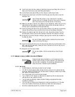
7)
Remove nut and washers from adjustment assembly if necessary (see
8)
Insert all-thread through round hole on adjustment side of angle iron.
9)
Place the flat washer, split washer and nut on all-thread.
Содержание NGC8206
Страница 1: ...2101510 rev AG NGC8206 Chromatograph User s Manual ...
Страница 14: ...xii Figure 6 3 AC Charger Power Supply Wiring 6 28 Figure 6 4 Communication Troubleshooting Flowchart 6 30 ...
Страница 27: ...Page 2 8 2101510 Rev AG Figure 2 4 NGC8206 Enclosure Figure 2 5 NGC8206 Enclosure Left Side ...
Страница 60: ...2101510 Rev AG Page 2 41 hex socket set screw on cap Figure 2 32 Explosion Proof AC Power Supply ...


