


2101510 Rev. AG
Page 6–15
5)
Verify that the peaks are correctly labeled and integrated. If the peaks are
correctly labeled and integrated, return the unit to operation.
6)
Allow unit to cycle 3-4 times.
7)
Following the
instructions in Startup, perform a calibration
ensuring that the Next Mode is set to
Hold
.
8)
Reset the Alarm Enable
to
Yes.
Verify that the alarm threshold
is a valid
configuration.
9)
Return the unit to regular operation.
The information provided for troubleshooting this alarm is only
intended to cover basic steps that can be performed in the
field. On occasion, additional troubleshooting steps may be
provided by Totalflow technical support in an effort to reduce
down time. Additionally, it may be desirable to return a
module to Totalflow for comprehensive testing and/or repair.
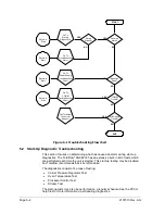
6.3.13 Enclosure Temperature Alarm
If the Enclosure Temperature alarm is in warning status, the following procedure
will step the user through the troubleshooting process. On occasion, these
instructions may detour the user to other procedures, and, when complete, they
should return to these procedures to continue.
6.3.13.1
Description
These alarms are indicative of either extremely high or low temperatures inside
the enclosure. Causes could range from external temperatures being extremely
high or low, to a bad temperature sensor on the analytical board.
6.3.13.2
Instructions
1)
Compare the outside temperature with the temperature reading on the Analyzer
Operation
screen, Enclosure Temperature. Atmospheric temperature could be
less than the enclosure temperature by as much as 20 degrees.
If the temperature differential seems reasonable, the unit may be operating
out of range. This unit is designed to operate between 0
8
F and 120
8
F.
2)
If the temperature differential does not seem reasonable, the analytical processor
assembly may have a bad temperature sensor. As this alarm is only a warning, it
will not effect the operation of the unit. The user may replace the analytical
module, as needed.
The Totalflow repair department offers a range of services for
troubleshooting and repairing/replacing the non-functioning
parts. For more information regarding the repair service,
contact customer service:
USA: (800) 442-3097 or International: 1-918-338-4880
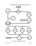
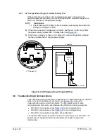
6.3.14 Power Supply Alarm
If the Power Supply alarm is in warning status, the following procedure will step
the user through the troubleshooting process. On occasion, these instructions may
detour the user to other procedures, and, when complete, they should return to
these procedures to continue.
6.3.14.1
Description
These alarms are indicative of input voltage either below 11 volts or above 16
volts. Causes may range from a power supply issue to a bad cable.
Содержание NGC8206
Страница 1: ...2101510 rev AG NGC8206 Chromatograph User s Manual ...
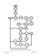
Страница 14: ...xii Figure 6 3 AC Charger Power Supply Wiring 6 28 Figure 6 4 Communication Troubleshooting Flowchart 6 30 ...
Страница 27: ...Page 2 8 2101510 Rev AG Figure 2 4 NGC8206 Enclosure Figure 2 5 NGC8206 Enclosure Left Side ...
Страница 60: ...2101510 Rev AG Page 2 41 hex socket set screw on cap Figure 2 32 Explosion Proof AC Power Supply ...


