


Page 5–22
2101510 Rev. AG
5.17 Replacing Feed-through Assembly
This section presents the procedures for the removal and installation of the feed-
through assembly. This assembly is located on the side of the NGC. Read through
all the procedural steps before removing the assembly.
Verify before beginning the procedure that the module is appropriately rated for
the system voltage. Compare the module voltage to the ID tag located on the side
of the enclosure.
5.17.1 Instructions
1)
On the Analyzer Operation
screen, click
Hold
under Next Mode. When the
unit completes the current cycle and enters hold, continue to the next step.
2)
Collect data from the unit.
3)
Back up the configuration files, following the instructions detailed previously in
the section, Backing Up Configuration Files.
4)
Using the Lithium Battery Status
instructions, verify the battery status is ok before
proceeding.
5)
Turn off all sample streams, calibration gas and carrier gas.
6)
Disconnect or remove the power from the NGC unit externally, or remove the J1
connector from the termination panel.
As with all electronic components, caution should be used
when handling boards. Static electricity can potentially
damage board components, voiding any warranty.
7)
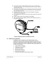
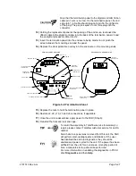
Gain access to the digital controller assembly by loosening the countersunk hex
socket locking set screw in the front end cap using a 1/16” hex wrench, then
unscrewing the end cap.
8)
Following the instructions detailed previously in the section,
, remove the assembly. If weather and circumstances
permit, the digital controller assembly may be suspended by the cables to
eliminate stress on the cable connections. If this is the case, move to step 10.
9)
Carefully unplug the cable to the termination panel, leaving the lithium battery
plugged in. Set the digital controller assembly aside on a clean, lint-free surface.
10)
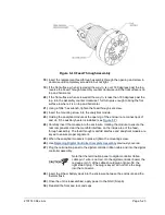
Using a 5/16” hex wrench, loosen the mounting screw holding the analytical
module in place until the module can be slowly lifted from the enclosure, taking
care to not pull the wires attached to the rear of the assembly.
11)
Detach the analytical module rear face jack J1 and J4, if the auxiliary heater is
installed.
12)
Set the module on a clean, lint-free surface.
13)
Using a ¼” open end wrench, loosen the Valco nut and remove the input line.
Repeat for all the sample, carrier and calibration gas lines.
14)
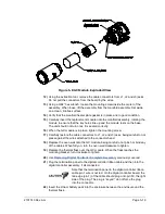
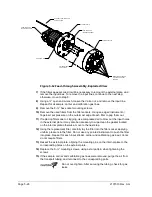
Using a 5/64” hex wrench, loosen the feed-through set screw.
15)
Unscrew the feed-through assembly, turning by hand counterclockwise until free.
16)
On the replacement assembly, install the O-ring and manifold gasket supplied
with new feed-through assembly (see
17)
Carefully apply the sealing thread lubricant to the threads on the feed-through
assembly, being extremely careful to not contaminate the feed-through manifold
and gasket.
Содержание NGC8206
Страница 1: ...2101510 rev AG NGC8206 Chromatograph User s Manual ...
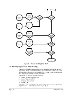
Страница 14: ...xii Figure 6 3 AC Charger Power Supply Wiring 6 28 Figure 6 4 Communication Troubleshooting Flowchart 6 30 ...
Страница 27: ...Page 2 8 2101510 Rev AG Figure 2 4 NGC8206 Enclosure Figure 2 5 NGC8206 Enclosure Left Side ...
Страница 60: ...2101510 Rev AG Page 2 41 hex socket set screw on cap Figure 2 32 Explosion Proof AC Power Supply ...


