


Page 6–16
2101510 Rev. AG
6.3.14.2
Instruction
1)
Check the power supply to the termination panel, following instructions later in
this chapter, Termination Panel Supply Voltage Test. If the test fails, restore the
power supply to proper working specifications; otherwise, continue to the next
step.
2)
Following the Cable Replacement instructions in Chapter 4, Maintenance, check
the analytical processor to termination panel cable for damage. If the cable is
damaged, replace; otherwise, continue to the next step.
3)
Following the Cable Replacement instructions in Chapter 4, Maintenance, check
the termination panel to digital controller cable for damage. If the cable is
damaged, replace; otherwise, contact Totalflow technical support for additional
instructions.
6.3.15 Low Carrier Gas Bottle (DI1) Alarm
If the Low Carrier Gas Bottle (DI1) alarm is in warning status, the following
procedure will step the user through the troubleshooting process. On occasion,
these instructions may detour the user to other procedures, and, when complete,
they should return to these procedures to continue.
6.3.15.1
Description
These alarms are indicative of the carrier gas bottle pressure below the threshold.
6.3.15.2
Instructions
1)
Verify that the carrier gas bottle regulator low pressure switch threshold is set
around 90 PSIG. The alarm is switched when pressure drops below the
threshold.
2)
If the threshold is above the current bottle PSIG, replace the carrier gas bottle.
3)
If the threshold is below the current bottle PSIG, verify the regulator is functioning
properly.
4)
Perform the
Abnormal Calibration Gas Depletion
procedure, found in this
chapter. If the procedure fails to locate the problem, contact Totalflow technical
support.
6.3.16 Low Cal Gas Bottle (DI2) Alarm
If the lo bottle calibration gas (DI2) alarm is in warning status, the following
procedure will step the user through the troubleshooting process. On occasion,
these instructions may detour the user to other procedures, and, when complete,
they should return to these procedures to continue.
6.3.16.1
Description
These alarms are indicative of the calibration gas bottle pressure below the
threshold.
6.3.16.2
Instructions
1)
Verify that the calibration gas bottle regulator low pressure switch threshold is set
around 15 PSIG. The alarm is switched when the pressure drops below the
threshold.
2)
If the threshold is above the current bottle PSIG, replace the calibration gas
bottle.
3)
If the threshold is below the current bottle PSIG, verify the regulator is functioning
properly.
Содержание NGC8206
Страница 1: ...2101510 rev AG NGC8206 Chromatograph User s Manual ...
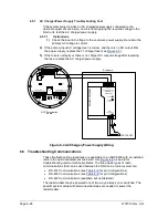
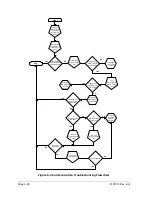
Страница 14: ...xii Figure 6 3 AC Charger Power Supply Wiring 6 28 Figure 6 4 Communication Troubleshooting Flowchart 6 30 ...
Страница 27: ...Page 2 8 2101510 Rev AG Figure 2 4 NGC8206 Enclosure Figure 2 5 NGC8206 Enclosure Left Side ...
Страница 60: ...2101510 Rev AG Page 2 41 hex socket set screw on cap Figure 2 32 Explosion Proof AC Power Supply ...


