


Page 5–16
2101510 Rev. AG
11)
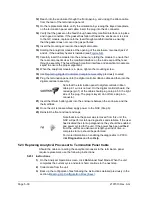
Detach the analytical module rear face jack J1 and J4, if the auxiliary heater is
installed (see
12)
Set module on a clean, lint-free surface.
13)
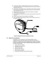
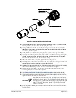
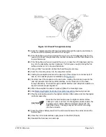
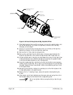
Verify that the gasket on the feed-through assembly manifold interface is in
place, in good condition and free from metal filings or other contamination. If the
gasket has fallen off inside the enclosure or stuck to the GC module, replace
onto the feed-through manifold interface, ensuring that the gasket does not cover
the gas portholes.
14)
Verify the S1 auxiliary heater switch is set to the correct position. If using the
auxiliary feed-through heater, set the position to Normal.
15)
Insert the mounting screw into the analytical module.
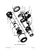
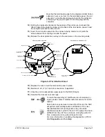
Figure 5-6 Analytical Module
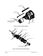
Figure 5-7 Analytical Processor Board
Содержание NGC8206
Страница 1: ...2101510 rev AG NGC8206 Chromatograph User s Manual ...
Страница 14: ...xii Figure 6 3 AC Charger Power Supply Wiring 6 28 Figure 6 4 Communication Troubleshooting Flowchart 6 30 ...
Страница 27: ...Page 2 8 2101510 Rev AG Figure 2 4 NGC8206 Enclosure Figure 2 5 NGC8206 Enclosure Left Side ...
Страница 60: ...2101510 Rev AG Page 2 41 hex socket set screw on cap Figure 2 32 Explosion Proof AC Power Supply ...


