


Page 5–18
2101510 Rev. AG
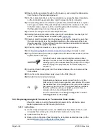
When the GC module is removed, the module should be
placed on a clean, dirt-free work surface. It is important that
the bottom surface of the module be placed on a clean, lint
free cloth to prevent its base from being scratched or
damaged. The gas sample flow line openings should be free
of foreign contaminants.
If the GC module is not being immediately replaced, put the
thermal flask back in place to prevent the mandrel from
being scratched or damaged and to keep the gas sample
flow line openings free of foreign contaminants. Also, be
careful with the miniature “D” type connector pins.
5.15.1 Instructions
1)
On the Analyzer Operation
screen, click
Hold
under Next Mode. When the
unit completes the current cycle and enters hold, continue to the next step.
2)
Collect data from the unit.
3)
Back up the configuration files, following the instructions detailed previously in
the section, Backing Up Configuration Files.
4)
Using the Lithium Battery Status
instructions, verify that the battery status is ok
before proceeding.
5)
Turn off all sample streams, calibration gas and carrier gas.
6)
Disconnect or remove the power from the NGC unit externally, or remove the J1
connector from the termination panel.
As with all electronic components, caution should be used
when handling boards. Static electricity can potentially
damage board components, voiding any warranty.
7)
Gain access to the digital controller assembly by loosening the countersunk hex
socket locking set screw in the front end cap using a 1/16” hex wrench then
unscrewing the end cap.
8)
Following the instructions detailed previously in the section,
, remove the assembly. If weather and circumstances
permit, the digital controller assembly may be suspended by the cables to
eliminate stress on cable connections. If so, move to step 10.
9)
Carefully unplug the cable to the termination panel, leaving the lithium battery
plugged in, and set the digital controller assembly aside on a clean, lint-free
surface.
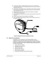
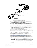
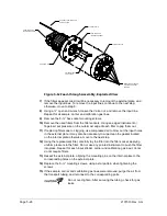
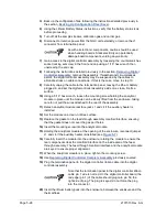
10)
Unscrew the thermal flask counterclockwise (see
). When loose, lift
the flask from the unit. Set aside.
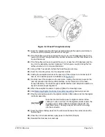
11)
Unscrew the oven wall counterclockwise (oven wall may be hot). When loose, lift
the cylinder from the GC module. Set aside.
Содержание NGC8206
Страница 1: ...2101510 rev AG NGC8206 Chromatograph User s Manual ...
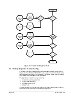
Страница 14: ...xii Figure 6 3 AC Charger Power Supply Wiring 6 28 Figure 6 4 Communication Troubleshooting Flowchart 6 30 ...
Страница 27: ...Page 2 8 2101510 Rev AG Figure 2 4 NGC8206 Enclosure Figure 2 5 NGC8206 Enclosure Left Side ...
Страница 60: ...2101510 Rev AG Page 2 41 hex socket set screw on cap Figure 2 32 Explosion Proof AC Power Supply ...


