


2101510 Rev. AG
Page 5–27
5.20 Replacing Feed-through Interface Gasket
Should the feed-through interface gasket require replacement (see
),
follow these instructions. Typically, the user would change the gasket while
performing another procedure, but for the purposes of this manual, the instructions
will start and finish as a complete procedure.
5.20.1 Instructions
1)
On the Analyzer Operation
screen, click
Hold
under Next Mode. When the
unit completes the current cycle and enters hold, continue to the next step.
2)
Collect data from the unit.
3)
Back up the configuration files, following the instructions detailed previously in
the section,
Backing Up Configuration Files (Save)
4)
Turn off all the sample streams, calibration gas and carrier gas.
5)
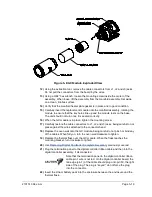
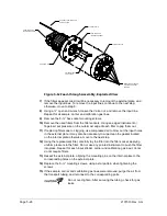
Using a 7/32” hex wrench, loosen and remove all 8–¼” hex socket screws.
6)
If space permits, lift the external plate away from the internal plate and remove
the damaged gasket from the internal plate. If space does not permit lifting the
plate away enough to replace the gasket, remove the sample input lines and the
carrier and calibration gas lines.
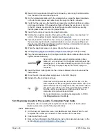
7)
Remount the external plate and remove the input lines. To remove the input
lines, continue to the next step; otherwise, skip to step 8.
8)
Using a ¼” open end wrench, loosen the Valco nut and remove the input line.
Repeat for all sample, carrier and calibration gas lines.
9)
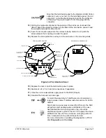
Remove the 8–¼” hex socket mounting screws.
10)
Remove the damaged gasket from the internal plate.
11)
Clean the gasket area on the internal plate using a clean, dry lint-free cloth
before placing the new gasket on the internal plate. The gasket is keyed to
ensure that it is placed correctly. The gasket should not cover any holes in the
internal plate.
12)
Reseat the external plate, aligning the mounting pins on the internal plate to the
corresponding holes on the external plate.
13)
Replace the 8–¼” mounting screws, using a star pattern when tightening the
screws.
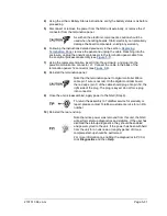
14)
If the sample, carrier and calibration gas lines were removed, purge air from the
transport tubing, and reconnect to the corresponding ports.
Do not over-tighten. After securing the tubing, check for gas
leaks.
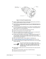
5.21 Replacing Feed-through Manifold Gasket
Should the feed-through manifold gasket require replacement (see
),
follow these instructions. Typically, the user would change the gasket while
performing another procedure, but for the purposes of this manual, the instructions
will start and finish as a complete procedure.
5.21.1 Instructions
1)
On the Analyzer Operation
screen, click
Hold
under Next Mode. When the
unit completes the current cycle and enters hold, continue to the next step.
2)
Collect data from the unit.
Содержание NGC8206
Страница 1: ...2101510 rev AG NGC8206 Chromatograph User s Manual ...
Страница 14: ...xii Figure 6 3 AC Charger Power Supply Wiring 6 28 Figure 6 4 Communication Troubleshooting Flowchart 6 30 ...
Страница 27: ...Page 2 8 2101510 Rev AG Figure 2 4 NGC8206 Enclosure Figure 2 5 NGC8206 Enclosure Left Side ...
Страница 60: ...2101510 Rev AG Page 2 41 hex socket set screw on cap Figure 2 32 Explosion Proof AC Power Supply ...


