


2101510 Rev. AG
Page 6–11
The information provided for troubleshooting this alarm is only
intended to cover basic steps that can be performed in the
field. On occasion, additional troubleshooting steps may be
provided by Totalflow technical support in an effort to reduce
down time. Additionally, it may be desirable to return a
module to Totalflow for comprehensive testing and/or repair.
6.3.6
No Stream Valve Selected
If the No Stream Valve Selected alarm is in system fault status, the following
procedure will step the user through the troubleshooting process. On occasion,
these instructions may detour the user to other procedures, and, when complete,
they should return to these procedures to continue.
6.3.6.1
Description
These alarms are indicative of an attempt to run a cycle with insufficient sample
pressure. If the sample pressure is too low when diagnostics are run, it will disable
all streams but continue to try and run chroms. This can also be caused if the
digital and analytical board moves out of synchronization.
6.3.6.2
Instructions
1)
Check the sampling system for leaks, tubing restrictions and incorrect pressure
settings. Repair the leak or restriction, or adjust the pressure setting, if found;
otherwise, continue to next step.
2)
Place the NGC in hold, allow ten minutes (approximately two cycles) to lapse and
then run a single cycle. If the alarm reappears, continue to the next step.
3)
The unit should still be in hold. Manually enable all streams.
4)
Perform start-up diagnostics. If the stream test fails, continue to the next step.
5)
Perform a warm start.
The information provided for troubleshooting this alarm is only
intended to cover basic steps that can be performed in the
field. On occasion, additional troubleshooting steps may be
provided by Totalflow technical support in an effort to reduce
down time. Additionally, it may be desirable to return a
module to Totalflow for comprehensive testing and/or repair.
6.3.7
Digital-Analog Board Communication Error Alarm
If the Digital-Analog Board Communication Error alarm is in system fault status,
the following procedure will step the user through the troubleshooting process. On
occasion, these instructions may detour the user to other procedures, and, when
complete, they should return to these procedures to continue.
6.3.7.1
Description
These alarms are indicative of a communication error between the digital board
and the analytical processor board. Verify the cable connectors are firmly and
correctly connected to both the digital and analytical processor boards.
6.3.7.2
Instructions
1)
In the alarm log, check the frequency of the error. If multiple errors exist, place
the unit in hold
and then launch a cycle.
2)
If the alarms continue to register, perform a warm start.
3)
When the unit completes the start-up diagnostics without error, place the unit in
run.
4)
Following 2-3 cycles, verify that no new alarms are registering.
Содержание NGC8206
Страница 1: ...2101510 rev AG NGC8206 Chromatograph User s Manual ...
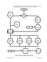
Страница 14: ...xii Figure 6 3 AC Charger Power Supply Wiring 6 28 Figure 6 4 Communication Troubleshooting Flowchart 6 30 ...
Страница 27: ...Page 2 8 2101510 Rev AG Figure 2 4 NGC8206 Enclosure Figure 2 5 NGC8206 Enclosure Left Side ...
Страница 60: ...2101510 Rev AG Page 2 41 hex socket set screw on cap Figure 2 32 Explosion Proof AC Power Supply ...


