


Page 3–48
2101510 Rev. AG
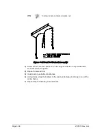
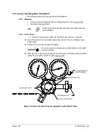
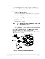
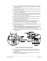
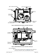
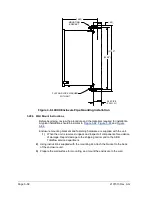
Figure 3-49 Thermostat Assembly Installed
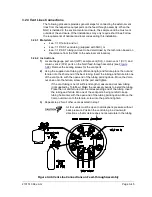
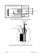
5)
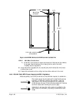
Screw the threaded end of the T assembly into the ¼” female fitting located on
the factory-installed Catalytic heater, by turning the entire assembly clockwise
until tight (see
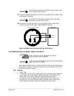
6)
Remove ferrules and nut from the bottom of the T assembly. Apply Teflon
®
tape
to threads.
7)
Insert the short bent end of the 3/8” tubing closest to the longest straight portion
of the tubing through the hole located below the catalytic heater.
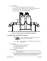
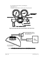
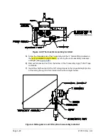
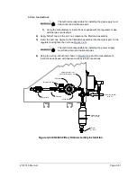
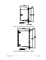
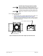
Figure 3-50 Regulator and Filter/Drain Assembly Installed
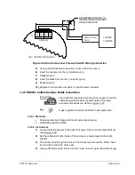
FILTER/DRAIN ASSEMBLIES
Содержание NGC8206
Страница 1: ...2101510 rev AG NGC8206 Chromatograph User s Manual ...
Страница 14: ...xii Figure 6 3 AC Charger Power Supply Wiring 6 28 Figure 6 4 Communication Troubleshooting Flowchart 6 30 ...
Страница 27: ...Page 2 8 2101510 Rev AG Figure 2 4 NGC8206 Enclosure Figure 2 5 NGC8206 Enclosure Left Side ...
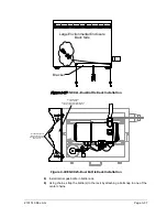
Страница 60: ...2101510 Rev AG Page 2 41 hex socket set screw on cap Figure 2 32 Explosion Proof AC Power Supply ...


