


2101510 Rev. AG
Page 5–21
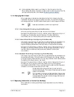
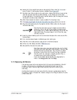
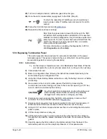
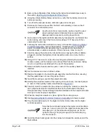
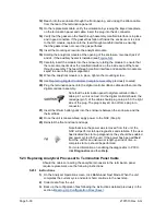
Note that the termination panel to the digital controller ribbon
cable pin 1 wire is not red. On the termination panel, the red
edge (pin 1) of cable should plug onto pin 50, the right side
of the plug. The plug is keyed; do not force plug into the
connector.
12)
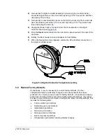
Holding the replacement panel at the opening of the enclosure, reconnect the
ribbon cable to the digital controller into the back of the termination panel J4 and
the analytical processor cable into J12.
13)
Insert the termination panel into the enclosure being careful to not pinch the
wires between the mounting stud and the panel.
14)
Replace the clear protective overlay into the enclosure on the mounting studs.
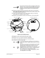
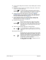
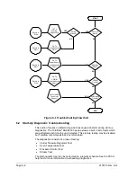
Figure 5-9 Termination Panel
15)
Replace the nuts to hold the termination panel in place.
16)
Restore J2, J8, J10, J3 and J6 connections, if applicable.
17)
Once the unit is reassembled, apply power to the NGC (Step 6).
18)
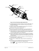
Reinstall the front and rear end caps.
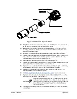
To return the assembly to Totalflow service for warranty or
repair, please contact Totalflow customer service for an RA
number.
Note that since power was removed from this unit, the NGC
will perform start-up diagnostics and stabilize. If the user
has disabled the start-up diagnostics, they should be
enabled and power cycled to the unit. If the power has been
withheld from the unit for an unknown or lengthy period of
time, a complete start-up should be performed.
For more information on enabling the diagnostics in PCCU,
click
Diagnostics
and then
Help
.
PRIMARY COMPONENT SIDE
SECONDARY COMPONENT SIDE
VR1
S2
UNSECU
R
E
SECURITY
ENABLED
STATUS
(-)
(+)
J4
ANALYTICAL PROCESSOR
CONNECTION
DIGITAL CONTROLLER
CONNECTION
USB CLIENT RECEPTICAL
ETHERNET STATUS INDICATORS
RESET
USB HOST RECEPTICAL
SERIAL PORT 1
SERIAL PORT 1
TERMINATION
LOCAL SERIAL DATA
CONNECTION
SECURITY SWITCH
DIGITAL I/O
POWER
ETHERNET
RECEPTICAL
SERIAL PORT 2
TERMINATION
SERIAL PORT 2
VOLTAGE
REGULATOR
SECURITY
SWITCH STATUS
OUTPUTS
D4
(-)
2
(-)
(+)
J7
POWER
D1
J9
D3
D2
5VDC
J2
J1
J6
1
J8
J5
3
2
5
4
7
6
9
8
D12 D11
J3
1
3
D13
S1
LINK
LAN
STAT
4
1
3
2
5
6
8
7
J10
9
J11
1
3
INPUTS
(-)
(-)
1
(+)
2
(+)
1
(+)
J12
Содержание NGC8206
Страница 1: ...2101510 rev AG NGC8206 Chromatograph User s Manual ...
Страница 14: ...xii Figure 6 3 AC Charger Power Supply Wiring 6 28 Figure 6 4 Communication Troubleshooting Flowchart 6 30 ...
Страница 27: ...Page 2 8 2101510 Rev AG Figure 2 4 NGC8206 Enclosure Figure 2 5 NGC8206 Enclosure Left Side ...
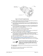
Страница 60: ...2101510 Rev AG Page 2 41 hex socket set screw on cap Figure 2 32 Explosion Proof AC Power Supply ...


