


Page 5–20
2101510 Rev. AG
23)
Turn on all sample streams, calibration gas and carrier gas.
24)
Once the unit is reassembled, apply power to the NGC (Step 6).
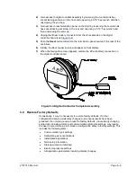
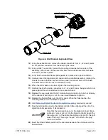
To return the assembly to Totalflow service for warranty or
repair, please contact Totalflow customer service for an RA
number.
25)
Follow the Cold Start procedure in
26)
Reinstall the front and rear end caps.
Note that since power was removed from this unit, the NGC
will perform start-up diagnostics and stabilize. If the user has
disabled the start-up diagnostics, they should be enabled and
power cycled to the unit. If power has been withheld from the
unit for an unknown or lengthy period of time, a complete
start-up should be performed.
For more information on enabling the diagnostics in PCCU,
click
Diagnostics
and then
Help
.
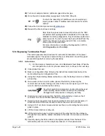
5.16 Replacing Termination Panel
This section presents the procedures for removal and installation of the power
termination panel. This panel is located in the rear of the NGC. Read through all
procedural steps before removing the assembly.
5.16.1 Instructions
1)
On the Analyzer Operation
screen, click
Hold
under Next Mode. When the
unit completes the current cycle and enters hold, continue to the next step.
2)
Collect data from unit.
3)
Back up configuration files, following the instructions detailed previously in the
section, Backing Up Configuration Files.
4)
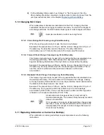
Using the Lithium Battery Status
instructions, verify the battery status is ok before
proceeding.
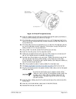
5)
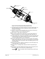
Gain access to the rear termination panel of the NGC by loosening the
countersunk hex socket locking set screw in the rear end cap using a 1/16” hex
wrench, and then unscrewing the end cap.
As with all electronic components, caution should be used
when handling boards. Static electricity can potentially
damage board components, voiding any warranty.
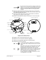
6)
Disconnect or remove power from the NGC unit externally, or remove the J1
connector from the termination panel (see
.
7)
Disconnect all connectors from board J2 digital I/O, J8 and J10 serial ports, J3
Ethernet and J6 USB client connectors. Move the wires out of the way.
8)
Using a 5/16” nut driver, loosen and remove the six nuts holding the termination
panel in place.
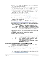
9)
Lift the clear protective overlay out.
10)
Lift the termination panel out, being careful of the wires fed into the enclosure
through the hubs and the cables connected to the back. Do not remove the EMI
gasket.
11)
Carefully unplug the ribbon cable to the digital controller from the back of the
termination panel J4 and the analytical processor J12. Set panel aside.
Содержание NGC8206
Страница 1: ...2101510 rev AG NGC8206 Chromatograph User s Manual ...
Страница 14: ...xii Figure 6 3 AC Charger Power Supply Wiring 6 28 Figure 6 4 Communication Troubleshooting Flowchart 6 30 ...
Страница 27: ...Page 2 8 2101510 Rev AG Figure 2 4 NGC8206 Enclosure Figure 2 5 NGC8206 Enclosure Left Side ...
Страница 60: ...2101510 Rev AG Page 2 41 hex socket set screw on cap Figure 2 32 Explosion Proof AC Power Supply ...


