


2101510 Rev. AG
Page 3–73
•
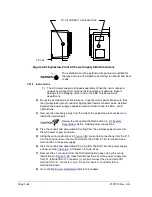
One 9-inch extension of 2-inch pipe or other suitable length of pipe, threaded
on one end.
•
One 2-inch coupling.
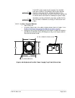
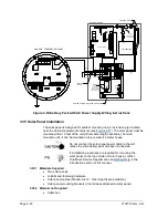
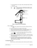
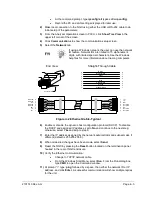
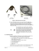
Exercise caution when installing the solar panel so as not
to damage it. When mounted, solar panel will face up from
horizon at 50° angle.
Figure 3-77 Typical Solar Panel Installation
3.35.3 Instructions
1)
Attach 2” pipe coupling to top end of enclosure mounting pipe. Securely
tighten.
2)
Install 2” pipe extension into coupling and securely tighten.
3)
Check solar panels using digital voltmeter to verify polarity and output voltage.
Voltage will vary depending on amount of sun and angle to the sun.
4)
Install solar panels on mounting bracket with provided hardware, if required.
Do not connect the other end of the solar panel cable to
the board until instructed to do so.
5)
Attach solar panel mounting plates to the top end of the 2” extension pipe with U-
bolts and associated mounting hardware. Do not tighten U-bolts until solar panels
are correctly positioned.
6)
For northern hemispheres, position solar panels facing south. For southern
hemispheres, position solar panels facing north. For optimum charging, solar
panels should not be in shadows for the majority of the day. Panels should be
kept clean for maximum charging.
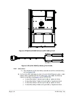
3.36 Solar Power Pack
Before beginning, review the procedure and the materials required for installation.
Solar Panel
Mounting Bracket
2 " Coupling
2 " Extension Pipe
Cable
Solar Panel
U - Bolts
Содержание NGC8206
Страница 1: ...2101510 rev AG NGC8206 Chromatograph User s Manual ...
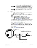
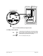
Страница 14: ...xii Figure 6 3 AC Charger Power Supply Wiring 6 28 Figure 6 4 Communication Troubleshooting Flowchart 6 30 ...
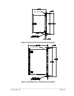
Страница 27: ...Page 2 8 2101510 Rev AG Figure 2 4 NGC8206 Enclosure Figure 2 5 NGC8206 Enclosure Left Side ...
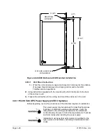
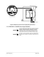
Страница 60: ...2101510 Rev AG Page 2 41 hex socket set screw on cap Figure 2 32 Explosion Proof AC Power Supply ...


