


Page 6–22
2101510 Rev. AG
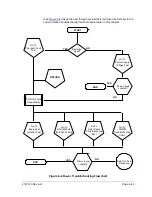
6.4.4
Feed-through Assembly Blockage Test
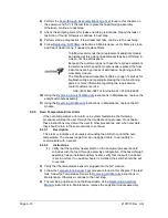
1)
Remove the feed-through assembly from the NGC following
2)
If testing from the pressure regulator 1 or 2 alarms, continue to steps 3 and 4.
If testing from the stream test in the start-up diagnostics or from the sample
pressure alarm, skip to step 5.
3)
Attach the pressure source to CV1 and activate. If the flow through assembly is
impeded, the test has failed. Return to troubleshooting alarm instructions;
otherwise, continue to next step.
4)
Attach the pressure source to CV2 and activate. If the flow through assembly is
impeded, the test has failed. Return to the column vent pressure test.
5)
Attach the pressure source to SV and activate. If the flow through assembly is
impeded, the test has failed. Return to the troubleshooting alarm instructions.
6.4.5
Temperature Sensor Test
6.4.5.1
Instructions
1)
Unplug the sensor from the GC module.
2)
Connect the digital multimeter (DMM) set to read resistance, positive lead to pin
1 and negative lead to pin 2.
3)
The meter should indicate a resistance reading between approximately 10 K
ohms and 1 M ohms. The resistance value is dependent on the temperature of
the gas chromatograph oven and ambient temperature; therefore, any reading in
this range should indicate a functioning temperature sensor.
6.4.6
Abnormal Calibration Gas Depletion
6.4.6.1
Description
If the calibration (and/or carrier) gas has depleted significantly sooner than
expected, there may one or more issues.
6.4.6.2
Instructions
1)
If the NGC has been running normally but consuming too much calibration
(and/or carrier) gas, carefully leak-test the gas bottle regulator, tubing and
connections to the NGC.
2)
If the unit is new start-up installation, check and tighten the analytical module
mounting bolt. The module may have been loosened due to vibration during
shipping.
3)
If the unit has been disassembled recently, re-check and tighten all assemblies
including the analytical module mounting bolt.
4)
If the NGC has been powered down for any significant length of time, the
calibration (also carrier and sample) gas should be shut off. Some valves may be
left in an open or partially open state allowing gas to continue flowing.
6.5 Power Troubleshooting
6.5.1
Overview
This section focuses on determining what has caused the NGC to lose power.
Generally, the loss of power can be attributed to only the power supply system.
However, if the power supply system is used for powering a transceiver, or other
peripheral equipment, a problem with that equipment may drain the battery and
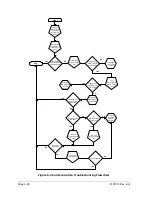
cause the NGC to lose power. Notice that the power troubleshooting flowchart
Содержание NGC8206
Страница 1: ...2101510 rev AG NGC8206 Chromatograph User s Manual ...
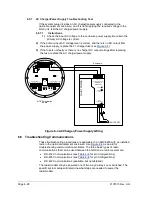
Страница 14: ...xii Figure 6 3 AC Charger Power Supply Wiring 6 28 Figure 6 4 Communication Troubleshooting Flowchart 6 30 ...
Страница 27: ...Page 2 8 2101510 Rev AG Figure 2 4 NGC8206 Enclosure Figure 2 5 NGC8206 Enclosure Left Side ...
Страница 60: ...2101510 Rev AG Page 2 41 hex socket set screw on cap Figure 2 32 Explosion Proof AC Power Supply ...


