


Page 3–42
2101510 Rev. AG
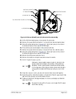
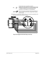
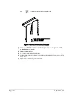
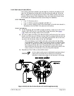
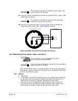
9)
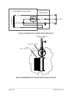
Insert the black wire into the (-) terminal (pin 4).
10)
Retighten pin 4.
11)
Replace the termination connector in the J2 board connector.
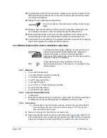
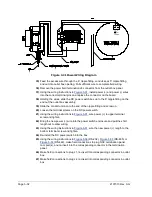
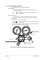
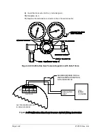
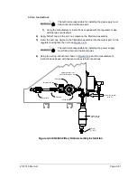
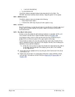
Figure 3-43 Calibration Gas Pressure Regulator with Relief Valve
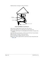
Figure
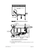
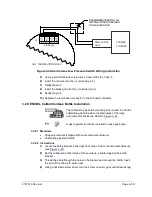
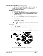
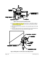
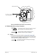
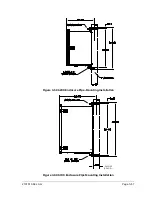
3-44 Calibration Blend Low Pressure Switch Wiring Instruction
ASSY
REGULATOR
CAL
BLEND
CYLINDER
J2
(-)
(+)
(-)
(+)
(-)
(+)
(-)
(+)
INPUTS
OUTPUTS
1
1
2
2
DIGITAL I/0
NGC TERMINATION BOARD
BARRIER REQUIRED FOR ALL
INSTALLATIONS OTHER THAN
NON-HAZARDOUS
IN MAIN ENCLOSURE
Содержание NGC8206
Страница 1: ...2101510 rev AG NGC8206 Chromatograph User s Manual ...
Страница 14: ...xii Figure 6 3 AC Charger Power Supply Wiring 6 28 Figure 6 4 Communication Troubleshooting Flowchart 6 30 ...
Страница 27: ...Page 2 8 2101510 Rev AG Figure 2 4 NGC8206 Enclosure Figure 2 5 NGC8206 Enclosure Left Side ...
Страница 60: ...2101510 Rev AG Page 2 41 hex socket set screw on cap Figure 2 32 Explosion Proof AC Power Supply ...