Zaxcom Fusion User’s Manual______________________________________________________Chapter 1
27
8.
Reference 1 connector
Reserved for the future.
9.
Wordclock Output connector
Connect an external device requiring Wordclock output here.
10.
Serial / RS-422 connector
Connect an external control device, such as the Mix-12 mixer here.
11.
Timecode connector
Connect a standard 5-pin LEMO connector here. (See
Timecode Connector
, {
p.159
})
12.
USB port
Connect a Zaxcom approved USB keyboard here.
Right Side Description
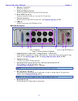
1. 2. 3. 4. 5. 1. 3.
Fusion-12 Right Side Fusion-10 Right Side Differences
Figure 1-3 Fusion-12 & Fusion-10 Right Sides
1.
Analog Outputs 1- 8 (Fusion-12) / Analog Outputs 1 - 6 (Fusion-10)
25-pin connector outputs 8 (or 6) channels of line-level audio. You can select the channels assigned to these
outputs from the
My Fusion page
{
p.104
}. (See
Analog Output Connector, DB-25
, {
p.158
})
2.
Headphone Output
1/4” stereo jack, optimal 100 ohm impedance.
3.
Line Inputs 9-12 Connector (Fusion-12) / Camera connector (Fusion-10)
This is a standard 10-pin Hirose connector. (See
Line Input / Camera Connector,
Hirose-10, {
p.158
}.)
NOTE:
For the Fusion-10, the two return monitor feeds are summed to mono.
4.
Mic / Line Inputs 1 through 8
Each balanced input is internally padded to handle either mic-level or line-level signals. The signal level is
selected using the
Analog Input (#) page
{
p.82
}.
NOTE:
Lower headphone impedance results in a higher headphone output level.
5.
Battery Ejection Pin
This pin ejects the NP-1 battery from its compartment.


