Zaxcom Fusion User’s Manual______________________________________________________Chapter 2
43
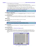
Limiter Matrix buttons
Each Output Channel flagged with an
X
has the limiter enabled for that channel. Settings for the limiter are
maintained by the
Output Limiter Settings page
{
p.44
}.
Routing Presets button
Pressing it takes you to the
Output Routing Presets page
{
p.46
}.
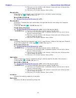
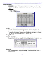
Output Routing button
This button displays three additional columns on the right used to flag the source of each output during Playback
mode, Stop mode and Record mode. With it displayed, pressing any of the boxes will turn ON/OFF audio coming
from the channel during each operation mode, indicated by a number if ON. The
Routing Presets
button
displays
the page that manages the underlying routing.
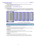
Normal
Play Switches
Play Tracks
Play Tracks
Mute Play
1-6, 11-12
5-12
Figure 2-9 Output Mix – Output Routing columns page
NOTE:
The Analog and Digital Outputs are essentially identical, with the exception that there are 6 Analog
Outputs and 8 Digital Outputs. Outputs 1 through 6 are the same in both groups.
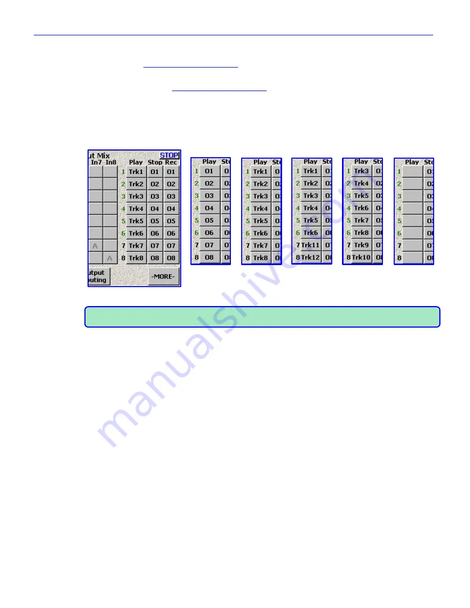
Play buttons
These indicate what will be sent to each output while the Fusion is in Play mode.
For example, if I have a Boom Operator on Output 1, and his audio is being recorded on track 1, I would set his
Play
button
to
Trk1
so he will be able to hear his audio during playback.
Stop buttons
These indicate what will be sent to each output while the Fusion is in Stop mode.
For example, if I don‟t want to have anyone hear any audio while in Stop mode, I can clear out all of the
Stop
button
s (leaving all of the
Stop
button
s blank).
Rec buttons
These indicate what will be sent to each output while the Fusion is in Record mode.
For example, if I have the mix being recorded on track 3 and I want to send it to the Director and Script
Supervisor on Output 3, I would set it to
03
and they will only hear the audio while we are recording a Take.


