


Setup screen
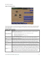
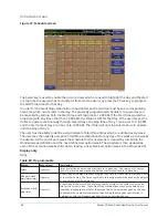
Figure 36: Setup screen
This screen is the top level of the general configuration parameters. It allows programming of the
time and date, along with specifications as to how the time will be displayed (12 or 24 hour format).
In addition, the chiller configuration, as determined by the state of the Microboard Program
Jumpers and Program Switches is displayed. A qualified Service Technician, following instructions
in
Service Manual (Form 160.69-M1-C)
, establishes this configuration per the desired operation. This
screen also serves as a gateway to more subscreens for defining general system parameters.
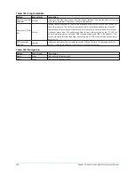
Table 86: Programmable
Button
Access level
Description
Refrigerant
selection
Service
Displays R134a or R22 as set by position of SW1-1 On = R134a.
Liquid type
Service
Displays Water or Brine as set by position of SW1-2 Off = Water.
Chilled liquid
pump operation Service
Displays as Standard or Enhanced.
Anti-recycle
Service
Selectable as Disabled or Enabled.
Power failure
restart
Service
Selectable as Manual or Automatic.
Motor drive type Service
Sets the type of Starter that is installed. EM, VSD - 60 Hz, VSD - 50 Hz, or MVVSD.
Coastdown time Service
Sets the Coastdown Time: Standard (150 seconds) or Enhanced (15 minutes – Steam
Turbine applications).
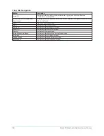
Pre-run
Operator
Sets the duration of the system pre-lube: Standard (50 seconds) or Extended (180
seconds).
Line frequency
Service
Sets the Line Frequency: 50 Hz or 60 Hz.
Motor heaters
Service
Is set to Enabled if optional Motor Heaters are installed or Disabled if they are not
installed.
Safety stop
Service
Displays Enabled, indicating that the Safety Stop switch is installed on the control
panel.
Model YD Mod D with OptiView Control Center
96
Summary of Contents for YD Mod D
Page 2: ...2 Model YD Mod D with OptiView Control Center...
Page 8: ...Nomenclature Model YD Mod D with OptiView Control Center 8...
Page 17: ...Figure 2 Chiller operation flow chart 17 Model YD Mod D with OptiView Control Center...
Page 18: ...Figure 2 Chiller operation flow chart Model YD Mod D with OptiView Control Center 18...
Page 19: ...Figure 2 Chiller operation flow chart 19 Model YD Mod D with OptiView Control Center...
Page 20: ...Figure 2 Chiller operation flow chart Model YD Mod D with OptiView Control Center 20...
Page 21: ...Figure 2 Chiller operation flow chart 21 Model YD Mod D with OptiView Control Center...
Page 22: ...Figure 2 Chiller operation flow chart Model YD Mod D with OptiView Control Center 22...
Page 150: ...Figure 57 Sample printout status Model YD Mod D with OptiView Control Center 150...
Page 151: ...Figure 57 Sample printout status 151 Model YD Mod D with OptiView Control Center...
Page 152: ...Figure 58 Sample printout setpoints Model YD Mod D with OptiView Control Center 152...
Page 153: ...Figure 58 Sample printout setpoints 153 Model YD Mod D with OptiView Control Center...
Page 154: ...Figure 59 Sample printout schedule Model YD Mod D with OptiView Control Center 154...
Page 155: ...Figure 60 Sample printout sales order 155 Model YD Mod D with OptiView Control Center...
Page 156: ...Figure 61 Sample printout history Model YD Mod D with OptiView Control Center 156...
Page 157: ...Figure 61 Sample printout history 157 Model YD Mod D with OptiView Control Center...
Page 159: ...Figure 64 Sample printout custom screen report 159 Model YD Mod D with OptiView Control Center...