


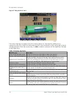


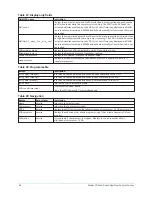


Table 8: Programmable
Button
Access level
Description
Local leaving
chilled liquid
temperature -
setpoint
Operator
This value allows the user to define the Leaving Chilled Liquid Temperature that is to
be maintained by the chiller. It is programmable over the range of 38.0°F to 70.0°F
(water) or 10.0°F to 70.0°F (brine). If Smart Freeze (see below) is enabled, the range is
36.0°F to 70.0°F (water). A remote device can provide an analog signal (0-20 mA, 4-20
mA, 0-10 VDC or 2-10 VDC) in Analog Remote mode, or PWM signal in Digital Remote
mode that changes the setpoint by creating an offset above the operator programmed
Base Leaving Chilled Liquid Temperature setpoint. This offset may be defined between
10.0°F and 40.0°F above the Base setpoint (see the Remote Leaving Chilled Liquid
Temperature Setpoint Range description below). Additionally, an SC-EQ (in ISN BAS
Remote mode) can define the setpoint through communications. In this case, the
incoming setpoint is not an offset, but rather is the setpoint value itself.
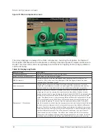
Local leaving
chilled liquid
temperature -
remote range
Operator
This is the range over which an analog (0-20 mA, 4-20 mA, 0-10 VDC or 2-10 VDC) in
Analog Remote Mode or a digital signal (PWM) in Digital remote mode can reset the
Leaving Chilled Liquid Temperature setpoint above the operator programmed Base
Setpoint. Programmable between 10°F and 40°F, with a default of 10°F, it is added to
the Base value to create a range over which the remote device can reset the setpoint.
For example, if this setpoint is programmed for 10°F and the operator programmed
value is 45°F, then the remote device can set the Leaving Chilled Liquid Temperature
setpoint over the range 45.0°F to 55.0°F.
Leaving
chilled liquid
temperature
cycling effective
offset - shutdown
Operator
This value allows the user to specify the Leaving Chilled Liquid Temperature at which
the chiller will shut down on a LEAVING CHILLED LIQUID – LOW TEMPERATURE
cycling shutdown. This is done by defining an offset below the Leaving Chilled Liquid
Temperature setpoint. It is programmable over a range of 1°F to 70°F below the
setpoint, to a minimum cutout of 36°F (water), 34°F (water with Smart Freeze enabled)
or 6°F (brine). It establishes the minimum allowable temperature for Model YD (Mod
D) with OptiView Control Center 37 the Leaving Chilled Liquid Temperature and
prevents over-cooling of the building. Anytime the Leaving Chilled Liquid Temperature
setpoint is increased, the shutdown threshold is 36.0°F (water) or 6.0°F (brine) and
then ramped up to the desired setpoint at the rate of 0.1°F/second. If Smart Freeze
(see below) is enabled, the initial threshold is 34.0°F.
Leaving
chilled liquid
temperature
cycling offset -
restart
Operator
This value allows the user to specify the Leaving Chilled Liquid Temperature at
which the chiller will restart after a shutdown on a LEAVING CHILLED LIQUID – LOW
TEMPERATURE cycling shutdown. This is done by defining an offset above the Leaving
Chilled Liquid Temperature setpoint. It is programmable over a range of 0°F to 35°F
above the setpoint, to a maximum restart value of 80°F. The chiller will automatically
restart when this temperature is reached. This setpoint can be used to reduce chiller
cycling by delaying the chiller restart until the cooling load has increased.
Brine low
evaporator cutout Service
This value is only available in Brine mode. It allows the user to specify the Evaporator
Pressure at which a safety shutdown is initiated.
Smart freeze (off/
on)
Service
This value is only available if the chiller is not in Brine mode. It allows the user to
enable the Smart Freeze Point Operation which allows the chiller to run closer to the
freeze point without shutting down.
Refrigerant
(enabled/
disabled)
Service
When an Evaporator Refrigerant Sensor has been installed it must be enabled via this
toggle before the system will utilize the sensor.
Table 9: Navigation
Button
Description
Home
Returns to the Home screen.
35
Model YD Mod D with OptiView Control Center
Summary of Contents for YD Mod D
Page 2: ...2 Model YD Mod D with OptiView Control Center...
Page 8: ...Nomenclature Model YD Mod D with OptiView Control Center 8...
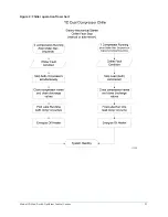
Page 17: ...Figure 2 Chiller operation flow chart 17 Model YD Mod D with OptiView Control Center...
Page 18: ...Figure 2 Chiller operation flow chart Model YD Mod D with OptiView Control Center 18...
Page 19: ...Figure 2 Chiller operation flow chart 19 Model YD Mod D with OptiView Control Center...
Page 20: ...Figure 2 Chiller operation flow chart Model YD Mod D with OptiView Control Center 20...
Page 21: ...Figure 2 Chiller operation flow chart 21 Model YD Mod D with OptiView Control Center...
Page 22: ...Figure 2 Chiller operation flow chart Model YD Mod D with OptiView Control Center 22...
Page 150: ...Figure 57 Sample printout status Model YD Mod D with OptiView Control Center 150...
Page 151: ...Figure 57 Sample printout status 151 Model YD Mod D with OptiView Control Center...
Page 152: ...Figure 58 Sample printout setpoints Model YD Mod D with OptiView Control Center 152...
Page 153: ...Figure 58 Sample printout setpoints 153 Model YD Mod D with OptiView Control Center...
Page 154: ...Figure 59 Sample printout schedule Model YD Mod D with OptiView Control Center 154...
Page 155: ...Figure 60 Sample printout sales order 155 Model YD Mod D with OptiView Control Center...
Page 156: ...Figure 61 Sample printout history Model YD Mod D with OptiView Control Center 156...
Page 157: ...Figure 61 Sample printout history 157 Model YD Mod D with OptiView Control Center...
Page 159: ...Figure 64 Sample printout custom screen report 159 Model YD Mod D with OptiView Control Center...