


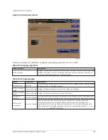


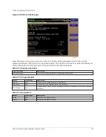


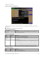

Comms screen
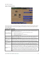
Figure 39: Comms screen
This screen allows definition of the necessary communications parameters. See
of the Printer connections and setup. Presently, there are no COM 2 communications features
available.
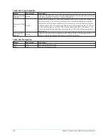
Table 92: Display only fields
Field/LED name
Description
COM 2 and COM 6 communication
parameters
The microboard will automatically change communication parameters until it finds the
correct settings to communicate with the starter logic boards. The starter type must
be entered correctly on the Setup Screen.
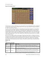
Table 93: Programmable
Button
Description
Chiller ID
Access level required: Operator
This ID number is printed at the top of reports obtained with a local printer.
Printer setup
Access level required: Operator
Pressing this key places a green selection box around the first changeable parameter.
Use the ▲ and ▼ keys to place the selection box around the desired parameter to be
changed. With the selection box around the desired parameter, press the
Enter
key. A
dialog box is displayed permitting data entry.
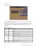
Printer baud rate
Define the baud rate at which the panel shall communicate to the printer.
Printer data bits
Defines the number of data bits with which the panel shall communicate to the
printer.
Printer parity bits
Define the number of parity bits with which the panel shall communicate to the
printer.
Printer stop bits
Define the number of stop bits with which the panel shall communicate to the printer.
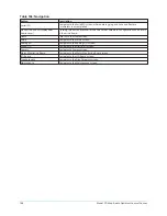
Table 94: Navigation
Button
Access level
Description
Home
View
Returns to the Home screen.
Setup
View
Returns to the Setup screen.
Model YD Mod D with OptiView Control Center
102
Summary of Contents for YD Mod D
Page 2: ...2 Model YD Mod D with OptiView Control Center...
Page 8: ...Nomenclature Model YD Mod D with OptiView Control Center 8...
Page 17: ...Figure 2 Chiller operation flow chart 17 Model YD Mod D with OptiView Control Center...
Page 18: ...Figure 2 Chiller operation flow chart Model YD Mod D with OptiView Control Center 18...
Page 19: ...Figure 2 Chiller operation flow chart 19 Model YD Mod D with OptiView Control Center...
Page 20: ...Figure 2 Chiller operation flow chart Model YD Mod D with OptiView Control Center 20...
Page 21: ...Figure 2 Chiller operation flow chart 21 Model YD Mod D with OptiView Control Center...
Page 22: ...Figure 2 Chiller operation flow chart Model YD Mod D with OptiView Control Center 22...
Page 150: ...Figure 57 Sample printout status Model YD Mod D with OptiView Control Center 150...
Page 151: ...Figure 57 Sample printout status 151 Model YD Mod D with OptiView Control Center...
Page 152: ...Figure 58 Sample printout setpoints Model YD Mod D with OptiView Control Center 152...
Page 153: ...Figure 58 Sample printout setpoints 153 Model YD Mod D with OptiView Control Center...
Page 154: ...Figure 59 Sample printout schedule Model YD Mod D with OptiView Control Center 154...
Page 155: ...Figure 60 Sample printout sales order 155 Model YD Mod D with OptiView Control Center...
Page 156: ...Figure 61 Sample printout history Model YD Mod D with OptiView Control Center 156...
Page 157: ...Figure 61 Sample printout history 157 Model YD Mod D with OptiView Control Center...
Page 159: ...Figure 64 Sample printout custom screen report 159 Model YD Mod D with OptiView Control Center...