


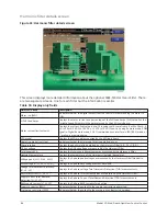


Motor details screen
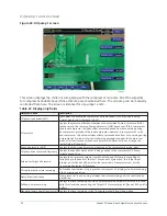
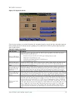
Figure 33: Motor details screen
This screen displays information pertinent to the optional Motor Monitoring feature. The feature
is an additional circuit board and sensors for each motor which can monitor motor winding
temperatures, motor bearing temperatures, motor bearing vibration and provide motor cooling
coil leak detection if installed.
The motor could be equipped with either RTD's or Thermistors for winding and bearing
temperature monitoring. Motor cooling coil leak detection could be done with either an optical or
float type of sensor.
This screen is similar for both Motor 1 and Motor 2.
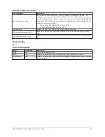
Table 78: Display only fields
Field/LED name
Description
Motor run (LED)
Lights when the OptiView Control Center is commanding the motor to run.
% Full Load Amps
Displays the motor current as a percentage of chiller Full Load Amps.
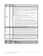
VSD output frequency
Only displayed when Motor Drive Type Setpoint is set to any VSD type. Displays the
frequency at which the VSD is operating the motor.
This value is provided by the VSD Logic Board.
PRV position
Displays the present Pre-rotation Vanes position as a value between 0% (closed) and
100% (full open).
Motor windings: Temperature
Displays the enabled Motor Winding Temperatures for phase A, B and C. When
winding RTD's are enabled, there are two temperatures displayed per phase. If
Thermistors are installed then only one temperature is displayed per phase. If any
sensor has failed and is disabled, its reading will not be displayed. Any RTD sensor that
registers as an open is considered invalid and displays as XXX.X.
Motor windings: Average winding
temperature
This value is calculated as the average of all enabled and valid Motor Winding
Temperatures. Any winding temperature that registers as open, out of range or
disabled is not used in the calculation. When RTD's are used for winding temperature
measurement, there are a maximum of six temperatures used to calculate the
average. When Thermistors are used, there are a maximum of three temperatures
used to calculate the average. The text description and data box do not appear when
the Winding Temperature Protection option is not installed.
Model YD Mod D with OptiView Control Center
88
Summary of Contents for YD Mod D
Page 2: ...2 Model YD Mod D with OptiView Control Center...
Page 8: ...Nomenclature Model YD Mod D with OptiView Control Center 8...
Page 17: ...Figure 2 Chiller operation flow chart 17 Model YD Mod D with OptiView Control Center...
Page 18: ...Figure 2 Chiller operation flow chart Model YD Mod D with OptiView Control Center 18...
Page 19: ...Figure 2 Chiller operation flow chart 19 Model YD Mod D with OptiView Control Center...
Page 20: ...Figure 2 Chiller operation flow chart Model YD Mod D with OptiView Control Center 20...
Page 21: ...Figure 2 Chiller operation flow chart 21 Model YD Mod D with OptiView Control Center...
Page 22: ...Figure 2 Chiller operation flow chart Model YD Mod D with OptiView Control Center 22...
Page 150: ...Figure 57 Sample printout status Model YD Mod D with OptiView Control Center 150...
Page 151: ...Figure 57 Sample printout status 151 Model YD Mod D with OptiView Control Center...
Page 152: ...Figure 58 Sample printout setpoints Model YD Mod D with OptiView Control Center 152...
Page 153: ...Figure 58 Sample printout setpoints 153 Model YD Mod D with OptiView Control Center...
Page 154: ...Figure 59 Sample printout schedule Model YD Mod D with OptiView Control Center 154...
Page 155: ...Figure 60 Sample printout sales order 155 Model YD Mod D with OptiView Control Center...
Page 156: ...Figure 61 Sample printout history Model YD Mod D with OptiView Control Center 156...
Page 157: ...Figure 61 Sample printout history 157 Model YD Mod D with OptiView Control Center...
Page 159: ...Figure 64 Sample printout custom screen report 159 Model YD Mod D with OptiView Control Center...