


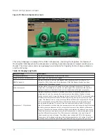


Table 31: Programmable
Button
Access level
Description
PRV VGD inhibit Service
(40% to 100%; default 90%). Applicable to dual compressor operation only. Both
VGD’s will be pulsed open according to the OPEN PULSE Setpoint as long as both
compressor’s PRV’s are above this value. While this is in effect, “PRV Position
Override” is displayed as Control Status.
PRV offset
Service
(0%-5%; default 3%) – This setpoint applies to both VGD controls. If the VGD control is
in the Stall Waiting state and the Pre-rotation vanes position changes by more than
this value, the Probing state will be entered. If the PRV Offset is set to 0%, the Stall
Waiting state is performed based only on the “Probe Wait Time” setpoint interval.
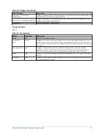
Surge react
Service
(1-30 seconds; default 5) – This setpoint applies to both VGD controls. Specifies the
length of the close pulse applied to the VGD in response to a surge.
Probe wait
Service
(0.5-15 minutes; default 10) – This setpoint applies to both VGD controls. Specifies
how long the VGD control remains in the Stall Waiting or Surge Waiting states before
entering the Probing state.
Open pulse
Service
(1-5 seconds; default 2) – This setpoint applies to both VGD controls. Specifies the
length of the open pulse applied to the VGD during 10 second periods while in the
Probing state.
Override delta
Service
(1% to 10%; default 5%) - This setpoint applies to both VGD controls. This setpoint
specifies the maximum allowed difference (1% to 10%) between the Lead VGD position
and the Lag VGD position while the VGD Position Override is in effect. The override
starts when the lag compressor pre-rotation vanes position is greater than or equal to
80% of the lead compressor pre-rotation vanes. While this override is in effect, if the
difference between the Lead VGD position and the Lag VGD position is greater than
the Override Delta setpoint, the VGD with the higher position is driven closed until it is
within the allowed difference. “VGD Position Override” is displayed as Control Status
while the override is in effect.
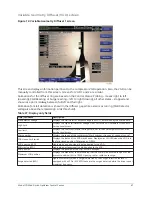
Extreme stall
duration
Service
(10 to 20 minutes; default 10) – This setpoint applies to both VGD controls. This
setpoint specifies the maximum allowed time an extreme stall condition can exist
before the VGD operation is disabled and driven to the full open (100%) position.
VGD 1: High limit Service
(0.5-1.2 VDC; default 0.8) – Specifies the Stall Detector Board output voltage that
represents an acceptable amount of stall noise. The minimum difference between the
High Limit setpoint and the Low Limit setpoint is 0.1 VDC.
If a Low Limit setpoint is entered which is less than 0.1 VDC below the High Limit
setpoint, the High Limit setpoint is adjusted so that it is 0.1 VDC above the newly
entered Low Limit value.
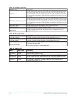
VGD 1: Low limit Service
(0.4-0.8 VDC; default 0.6) – in the Stall Reacting State, the VGD is driven closed until the
Stall Detector Board output voltage decreases to this level. The minimum difference
between the High Limit setpoint and the Low Limit setpoint is 0.1 VDC.
If a Low Limit setpoint is entered which is less than 0.1 VDC below the High Limit
setpoint, the High Limit setpoint is adjusted so that it is 0.1 VDC above the newly
entered Low Limit value.
VGD 2: High limit Service
(0.5-1.2 VDC; default 0.8) – Specifies the Stall Detector Board output voltage that
represents an acceptable amount of stall noise. The minimum difference between the
High Limit setpoint and the Low Limit setpoint is 0.1 VDC.
If a Low Limit setpoint is entered which is less than 0.1 VDC below the High Limit
setpoint, the High Limit setpoint is adjusted so that it is 0.1 VDC above the newly
entered Low Limit value.
VGD 2: Low limit Service
(0.4-0.8VDC; default 0.6) – in the Stall Reacting State, the VGD is driven closed until the
Stall Detector Board output voltage decreases to this level. The minimum difference
between the High Limit setpoint and the Low Limit setpoint is 0.1 VDC.
If a Low Limit setpoint is entered which is less than 0.1 VDC below the High Limit
setpoint, the High Limit setpoint is adjusted so that it is 0.1 VDC above the newly
entered Low Limit value.
Model YD Mod D with OptiView Control Center
50
Summary of Contents for YD Mod D
Page 2: ...2 Model YD Mod D with OptiView Control Center...
Page 8: ...Nomenclature Model YD Mod D with OptiView Control Center 8...
Page 17: ...Figure 2 Chiller operation flow chart 17 Model YD Mod D with OptiView Control Center...
Page 18: ...Figure 2 Chiller operation flow chart Model YD Mod D with OptiView Control Center 18...
Page 19: ...Figure 2 Chiller operation flow chart 19 Model YD Mod D with OptiView Control Center...
Page 20: ...Figure 2 Chiller operation flow chart Model YD Mod D with OptiView Control Center 20...
Page 21: ...Figure 2 Chiller operation flow chart 21 Model YD Mod D with OptiView Control Center...
Page 22: ...Figure 2 Chiller operation flow chart Model YD Mod D with OptiView Control Center 22...
Page 150: ...Figure 57 Sample printout status Model YD Mod D with OptiView Control Center 150...
Page 151: ...Figure 57 Sample printout status 151 Model YD Mod D with OptiView Control Center...
Page 152: ...Figure 58 Sample printout setpoints Model YD Mod D with OptiView Control Center 152...
Page 153: ...Figure 58 Sample printout setpoints 153 Model YD Mod D with OptiView Control Center...
Page 154: ...Figure 59 Sample printout schedule Model YD Mod D with OptiView Control Center 154...
Page 155: ...Figure 60 Sample printout sales order 155 Model YD Mod D with OptiView Control Center...
Page 156: ...Figure 61 Sample printout history Model YD Mod D with OptiView Control Center 156...
Page 157: ...Figure 61 Sample printout history 157 Model YD Mod D with OptiView Control Center...
Page 159: ...Figure 64 Sample printout custom screen report 159 Model YD Mod D with OptiView Control Center...