


Discharge #X – Valve Not Opened
appears. Upon entering prelube, the refrigerant level
control raise (close) output to the variable orifice is energized for the duration of the Valve Preset
Time setpoint (0 to 100 seconds). After this pre-positioning, the valve is held in this position for the
first 3 minutes of compressor operation.
Upon completion of the prelube period, the lead compressor motor is started and the
Chiller
Pulldown Period
begins. This period is in effect until the Leaving Chilled Liquid Temperature is
within 2ºF of the Leaving Chilled Liquid Temperature setpoint. During this period, the pre-rotation
vanes are modulated to achieve the Leaving Chilled Liquid Temperature setpoint. After the first
3 minutes of compressor operation and for the remainder of the Chiller Pulldown Period, the
rate of change of the Leaving Chilled Liquid Temperature is monitored to determine if the Lead
compressor is meeting the load demand requirements. The Leaving Chilled Liquid temperature
is sampled at 1 minute intervals. If the rate of change of the Liquid Temperature (
Delta T Rate
)
is less than the programmed
Minimum Rate setpoint
(0.5ºF/minute to 2.0ºF/minute; default
1.0ºF/minute) for a period equal to the
Minimum Rate Time setpoint
(1 to 20 minutes; default 5
minutes) and the Pulldown Demand Limit setpoint is above 50%, the lag compressor is brought on
line. If a Lead Compressor Pulldown Demand Limit setpoint has been entered, the lag compressor
will not be brought on line until this time has elapsed.
When the first 3 minutes of compressor operation has elapsed, if the refrigerant level is greater
than or equal to the
Level Control setpoint
, the level is controlled to the Level setpoint. However,
if the level is less than the Level Control setpoint, a linearly increasing ramp called the
Refrigerant
Level Target
is applied to the Level Control setpoint. This ramp allows the level to go from the
present level to the Level Control Setpoint over a period programmed as the
Ramp Up Time
setpoint
. After the ramp up time has elapsed, the level is controlled to the Level Control setpoint.
After the Chiller pulldown period ends, if the lag compressor has not been brought on line during
the chiller pulldown period, the
Chiller Steady State Period
begins. During this period, the pre-
rotation vanes are modulated to maintain the Leaving Chilled Liquid Temperature Setpoint.
In order to determine if the Lead compressor is meeting the load demand during this period,
the Leaving Chilled Liquid Temperature minus the Leaving Chilled Liquid Temperature Setpoint
(
Temperature Differential
) is monitored. If the
Temperature Differential
exceeds the
Maximum
Delta T setpoint
(1.0 ºF to 5.0 ºF; default 1.0) for a period equal to the
Maximum Delta T Time
setpoint
(1 to 20 minutes; default 5) and the Chiller Current Limit setpoint is above 50%, the lag
compressor is brought online.
With only one compressor running, the compressor variable geometry diffuser is modulated
according to the stall and surge activity.
When bringing the lag chiller on line, it enters the prelube period. If a high head condition exists,
the lead compressor’s pre-rotation vanes are driven closed as described in
. The Refrigerant Level Control Lag Start mode is initiated as described in
refrigerant level control – lag start
. During the Lag Prelube, all normal Prelube functions are
performed except the Oil Pressure Transducer Offset calibration is not performed. The offset
calculation from the Lead compressor start is used. The Prelube time is fixed at 50 seconds. At the
completion of the Prelube, the Lag compressor motor is started and after a 50 second delay, the
lag compressor discharge valve is opened. If it doesn’t fully open within 40 seconds as indicated
by the Discharge Valve Limit Switch, a Safety shutdown is performed on both compressors and
Discharge #X – Valve Not Opened
is displayed. After the discharge valve has fully opened,
the lag compressor pre-rotation vanes are modulated to follow lead motor current. Meanwhile, the
lead compressor pre-rotation vanes have been modulated to maintain the Leaving Chilled Liquid
Temperature setpoint, unless
Lag compressor start with high head
When the lag motor current is 5% of the lead motor current, the run time of the
compressors are evaluated to determine which can be the lead compressor. The one with the least
amount of run time is identified as the lead compressor. If a
Lag compressor start with high head
was performed, the lead pre-rotation vanes can now open and are controlled according to the
Leaving Chilled Liquid Temperature setpoint. Two minutes after the lag compressor discharge valve
11
Model YD Mod D with OptiView Control Center
Summary of Contents for YD Mod D
Page 2: ...2 Model YD Mod D with OptiView Control Center...
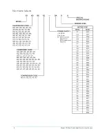
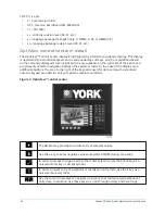
Page 8: ...Nomenclature Model YD Mod D with OptiView Control Center 8...
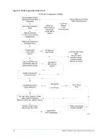
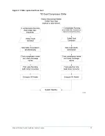
Page 17: ...Figure 2 Chiller operation flow chart 17 Model YD Mod D with OptiView Control Center...
Page 18: ...Figure 2 Chiller operation flow chart Model YD Mod D with OptiView Control Center 18...
Page 19: ...Figure 2 Chiller operation flow chart 19 Model YD Mod D with OptiView Control Center...
Page 20: ...Figure 2 Chiller operation flow chart Model YD Mod D with OptiView Control Center 20...
Page 21: ...Figure 2 Chiller operation flow chart 21 Model YD Mod D with OptiView Control Center...
Page 22: ...Figure 2 Chiller operation flow chart Model YD Mod D with OptiView Control Center 22...
Page 150: ...Figure 57 Sample printout status Model YD Mod D with OptiView Control Center 150...
Page 151: ...Figure 57 Sample printout status 151 Model YD Mod D with OptiView Control Center...
Page 152: ...Figure 58 Sample printout setpoints Model YD Mod D with OptiView Control Center 152...
Page 153: ...Figure 58 Sample printout setpoints 153 Model YD Mod D with OptiView Control Center...
Page 154: ...Figure 59 Sample printout schedule Model YD Mod D with OptiView Control Center 154...
Page 155: ...Figure 60 Sample printout sales order 155 Model YD Mod D with OptiView Control Center...
Page 156: ...Figure 61 Sample printout history Model YD Mod D with OptiView Control Center 156...
Page 157: ...Figure 61 Sample printout history 157 Model YD Mod D with OptiView Control Center...
Page 159: ...Figure 64 Sample printout custom screen report 159 Model YD Mod D with OptiView Control Center...