


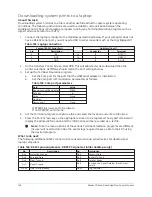


Downloading system prints to a laptop
About this task:
Downloading system histories to a file is another useful method to capture system operating
conditions. The following instructions are used to establish communication between the
OptiView Control Panel and a laptop computer running any Terminal Emulation program such as
HyperTerminal, TeraTerm, or PuTTy.
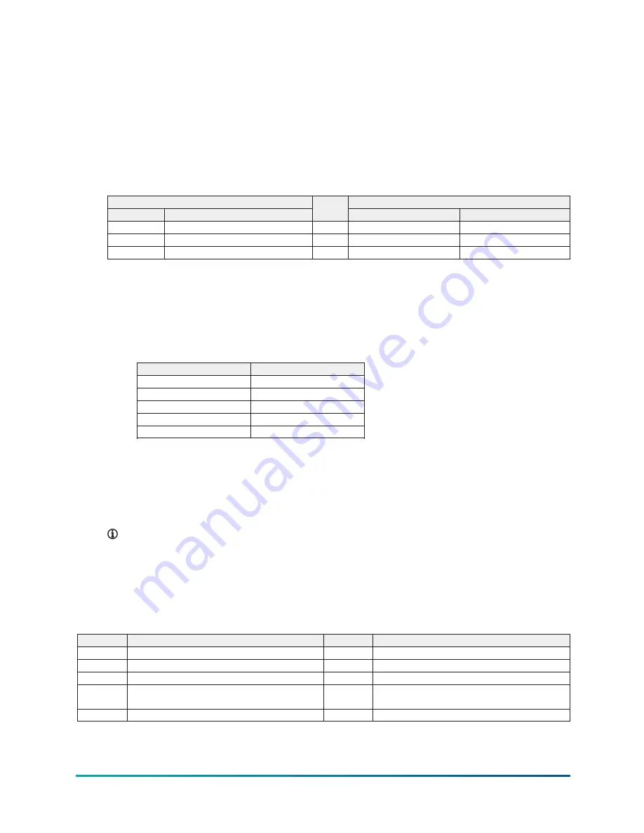
1. Connect the laptop computer to the OptiView as described below. If your computer does not
have a RS-232 serial port, you will need a USB to serial converter such as the Digi Edgeport/1.
Table 144: Laptop connection
Laptop (RS-232 Serial Port)
OptiView (Com 1)
Pin
Description
Connector
Terminal
2
RX
to
J2
4 (TXD1)
4
DTR
to
J2
2 (DSR1)
5
GND
to
J2
8 GND
2. On the OptiView Printer Screen, select
PC
. This will allow faster data download than the
printer selections. SETTINGS should match the Port settings below.
3. Set up the Terminal Emulation program.
a.
Set the Com port for the port that the USB/Serial adapter is installed on.
b.
Set the Com port communication parameters as follows:
Table 145: Com port parameters
Field
Value
Bits per second (Baud Rate)
57600
Data bits
8
Parity
None
Stop Bits
1
Flow control
None
If DTR/DSR is used, set to Hardware.
If no DTR/DSR, set to None.
4. Set the Terminal program to capture a file, and select the location and enter a file name.
5. Press the Print Screen key on the appropriate screen to be captured. The HyperTerminal will
display the printed information and the information will be recorded as a .txt file.
Note:
Since the menu options of the various Terminal Emulation programs are different,
the user will need to determine the exact steps required to save a file to their PC using
the desired program.
What to do next:
The following additional RS232 connections are used to wire up serial devices for desktop and
laptop computers.
Table 146: RS-232 pin assignments - DB25 PC signal set (older desktops only)
Pin
Description
Pin
Description
Pin 1
Protective Ground
Pin 2
Transmit Data
Pin 3
Received Data
Pin 4
Request To Send
Pin 5
Clear To Send
Pin 6
Data Set Ready
Pin 7
Signal Ground
Pin 8
Received line Signal Detector (Data Carrier
Detect)
Pin 20
Data Terminal Ready
Pin 22
Ring Indicator
Model YD Mod D with OptiView Control Center
148
Summary of Contents for YD Mod D
Page 2: ...2 Model YD Mod D with OptiView Control Center...
Page 8: ...Nomenclature Model YD Mod D with OptiView Control Center 8...
Page 17: ...Figure 2 Chiller operation flow chart 17 Model YD Mod D with OptiView Control Center...
Page 18: ...Figure 2 Chiller operation flow chart Model YD Mod D with OptiView Control Center 18...
Page 19: ...Figure 2 Chiller operation flow chart 19 Model YD Mod D with OptiView Control Center...
Page 20: ...Figure 2 Chiller operation flow chart Model YD Mod D with OptiView Control Center 20...
Page 21: ...Figure 2 Chiller operation flow chart 21 Model YD Mod D with OptiView Control Center...
Page 22: ...Figure 2 Chiller operation flow chart Model YD Mod D with OptiView Control Center 22...
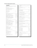
Page 150: ...Figure 57 Sample printout status Model YD Mod D with OptiView Control Center 150...
Page 151: ...Figure 57 Sample printout status 151 Model YD Mod D with OptiView Control Center...
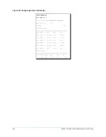
Page 152: ...Figure 58 Sample printout setpoints Model YD Mod D with OptiView Control Center 152...
Page 153: ...Figure 58 Sample printout setpoints 153 Model YD Mod D with OptiView Control Center...
Page 154: ...Figure 59 Sample printout schedule Model YD Mod D with OptiView Control Center 154...
Page 155: ...Figure 60 Sample printout sales order 155 Model YD Mod D with OptiView Control Center...
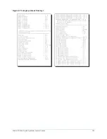
Page 156: ...Figure 61 Sample printout history Model YD Mod D with OptiView Control Center 156...
Page 157: ...Figure 61 Sample printout history 157 Model YD Mod D with OptiView Control Center...
Page 159: ...Figure 64 Sample printout custom screen report 159 Model YD Mod D with OptiView Control Center...