


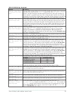


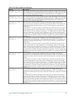


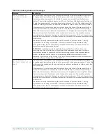


Table 143: Safety shutdown messages
Message
Description
OIL PUMP #2 – SETPOINT
NOT ACHIEVED
The chiller (both compressors) has shutdown because compressor #2 differential oil
pressure, as sensed by compressor #2 Pump transducer and the Sump transducer, failed to
meet the following requirements:
•
The differential oil pressure was <35.0 psid for 5 continuous seconds during the last
10 seconds of compressor #2 prelube or during the first 15 seconds of compressor #2
run.
-OR-
•
After the first 30 seconds of compressor #2 run, the differential oil pressure was < the
Setpoint/Target oil pressure with the oil pump drive speed command at 60 Hz for 5
continuous seconds.
The chiller can be started after the Operator presses the Clear Faults button.
SURGE PROTECTION –
EXCESS SURGE
(Applies only to single compressor operation and if the Surge Protection SHUTDOWN
setpoint is enabled).
The running compressor has shutdown because the Surge Window Count exceeded the
Count Limit setpoint. If the Surge Protection Extended Run feature is Disabled, the chiller
shutsdown as soon as the count exceeds the limit. If the Extended Run feature is Enabled,
this shutdown occurs only if the Surge Window Count exceeds the Count Limit setpoint
at completion of the 10 minute Extended Run period. The chiller can be started after the
Operator presses the Clear Faults button.
CONDENSER – HIGH
PRESSURE
The condenser pressure, as sensed by the Condenser Transducer, has increased to >180.0
psig (R-134a). The chiller can be started after the pressure decreases to < 120.0 psig (R-134a),
and the Operator presses the Clear Faults button.
CONDENSER – PRESSURE
TRANSDUCER OUT OF RANGE
The Condenser Pressure Transducer is indicating a pressure that is < 6.8 psig (R-134a), or
> 300.0 psig (R-134a). This is outside the normal operating range of the transducer. This is
generally indicates a defective transducer. The chiller can be started after the transducer is
indicating a pressure that is within range and the Operator presses the Clear Faults button.
CONTROL PANEL – POWER
FAILURE
A Control Power failure has occurred. If the power failure duration was < the duration of
the applicable “Coastdown” period (2.5 minutes standard; 15 minutes steam turbine), the
remainder of the “Coastdown” is performed upon restoration of power. The chiller can
be started after the Operator presses the Clear Faults button. This message can indicate
a Cycling (auto-restart after power failure) or Safety (manual restart after power failure)
shutdown, depending upon Control Center configuration. It indicates a Cycling shutdown
when displayed in orange characters; Safety shutdown when displayed in red characters.
The Control center is configured for auto-restart or manual restart after power failure by a
qualified Service technician.
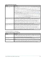
THRUST BEARING #1
– PROXIMITY PROBE
CLEARANCE
The chiller (both compressors) has shutdown because the clearance between Compressor
#1 high speed thrust collar and the tip of the proximity Probe has increased > +10 mils
(instantaneous) or decreased > -25 mils (for 2 continuous seconds) from the Reference
Position. The minimum allowed clearance is 23 mils. Therefore, if the Reference Position is <
47 mils, the shutdown will occur when the actual position is < 22 mils. The chiller cannot be
started until the special reset procedure is performed as referenced in the CAUTION below.
If compressor #1 is locked-out using the Lockout key on the Capacity Compressor Cycling
Screen, this fault does not cause compressor #2 to shutdown or prevent it from starting.
When this fault occurs on a locked-out compressor, it is displayed as a warning. This allows
the user to know that a fault exists on the locked-out compressor. The condition must be
corrected prior to the lockout being removed from the compressor. If it is not, the warning
condition will revert back to a shutdown as soon as the lockout is removed and will cause the
chiller to trip.
The clearance is only checked during the last 20 seconds of “System Prelube”, during
“System Run” and during “Coastdown”. Therefore, the fault is only detected during those
periods. Also, the +10 mil threshold must be exceeded for 2 continuous seconds.
Model YD Mod D with OptiView Control Center
144
Summary of Contents for YD Mod D
Page 2: ...2 Model YD Mod D with OptiView Control Center...
Page 8: ...Nomenclature Model YD Mod D with OptiView Control Center 8...
Page 17: ...Figure 2 Chiller operation flow chart 17 Model YD Mod D with OptiView Control Center...
Page 18: ...Figure 2 Chiller operation flow chart Model YD Mod D with OptiView Control Center 18...
Page 19: ...Figure 2 Chiller operation flow chart 19 Model YD Mod D with OptiView Control Center...
Page 20: ...Figure 2 Chiller operation flow chart Model YD Mod D with OptiView Control Center 20...
Page 21: ...Figure 2 Chiller operation flow chart 21 Model YD Mod D with OptiView Control Center...
Page 22: ...Figure 2 Chiller operation flow chart Model YD Mod D with OptiView Control Center 22...
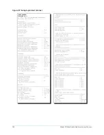
Page 150: ...Figure 57 Sample printout status Model YD Mod D with OptiView Control Center 150...
Page 151: ...Figure 57 Sample printout status 151 Model YD Mod D with OptiView Control Center...
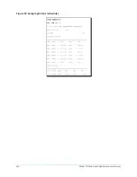
Page 152: ...Figure 58 Sample printout setpoints Model YD Mod D with OptiView Control Center 152...
Page 153: ...Figure 58 Sample printout setpoints 153 Model YD Mod D with OptiView Control Center...
Page 154: ...Figure 59 Sample printout schedule Model YD Mod D with OptiView Control Center 154...
Page 155: ...Figure 60 Sample printout sales order 155 Model YD Mod D with OptiView Control Center...
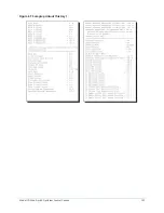
Page 156: ...Figure 61 Sample printout history Model YD Mod D with OptiView Control Center 156...
Page 157: ...Figure 61 Sample printout history 157 Model YD Mod D with OptiView Control Center...
Page 159: ...Figure 64 Sample printout custom screen report 159 Model YD Mod D with OptiView Control Center...