


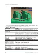


Oil sump screen
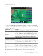
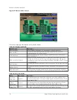
Figure 25: Oil sump screen
This screen displays a close-up of the chiller oil sump with pertinent oil system status, pressures
and temperatures. This screen also serves as a gateway to subscreens that allow programming of
setpoints for the Variable Speed Oil Pumps for compressor #1 and #2.
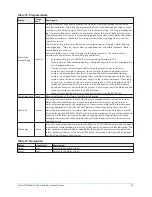
Table 58: Display only fields
Field/LED name
Description
Oil heater (LED)
Lights when the oil heater output is energized.
System oil return solenoid (LED)
Lights when the oil solenoid output is energized.
Oil sump temperature
Displays the temperature of the oil in the sump.
Sump oil pressure (LOP)
Displays the low side oil pressure measured at the sump.
Oil pump 1: Oil pump run output
(LED)
Illuminates when compressor #1 Variable Speed Oil Pump is being commanded to
run.
Oil pump 1: Pump oil pressure
(HOP)
Displays the high side oil pressure measured at the compressor #1 bearing input.
Oil pump 1: Oil pressure
Displays the pressure differential between the Pump oil pressure (HOP) transducer
for compressor #1 and the common Sump oil pressure (LOP) transducer. If this
compressor is the lead compressor, includes offset pressure derived from auto-
zeroing during the compressor #1 pre-lube. However, if compressor #2 is the lead
compressor, this value includes offset pressure derived from auto-zeroing during
compressor #2 Pre-lube (refer to auto-zeroing explanation under the Compressor
Screen). If either transducer used to calculate this differential is out of range, the
display field will show XX.X.
Oil pump 1: Oil pump drive
command frequency
Displays the speed command applied to compressor #1 Variable Speed Oil Pump.
Oil pump 1: Setpoint or target oil
pressure
Displays the oil pressure setpoint that compressor #1 Variable Speed Oil Pump is
controlling to. During the pre-lube and for the first 15 seconds of System Run, this is
the target Setpoint, and is fixed at 45.0 PSID. For the remainder of compressor #1 run,
it is the programmed Setpoint Oil Pressure.
Oil pump 1: Pulldown time
remaining
Displays the time remaining until the user programmed Setpoint Oil Pressure is used.
While this clock is decrementing, the Target Oil Pressure Setpoint (fixed at 45.0 psid) is
in effect.
Model YD Mod D with OptiView Control Center
72
Summary of Contents for YD Mod D
Page 2: ...2 Model YD Mod D with OptiView Control Center...
Page 8: ...Nomenclature Model YD Mod D with OptiView Control Center 8...
Page 17: ...Figure 2 Chiller operation flow chart 17 Model YD Mod D with OptiView Control Center...
Page 18: ...Figure 2 Chiller operation flow chart Model YD Mod D with OptiView Control Center 18...
Page 19: ...Figure 2 Chiller operation flow chart 19 Model YD Mod D with OptiView Control Center...
Page 20: ...Figure 2 Chiller operation flow chart Model YD Mod D with OptiView Control Center 20...
Page 21: ...Figure 2 Chiller operation flow chart 21 Model YD Mod D with OptiView Control Center...
Page 22: ...Figure 2 Chiller operation flow chart Model YD Mod D with OptiView Control Center 22...
Page 150: ...Figure 57 Sample printout status Model YD Mod D with OptiView Control Center 150...
Page 151: ...Figure 57 Sample printout status 151 Model YD Mod D with OptiView Control Center...
Page 152: ...Figure 58 Sample printout setpoints Model YD Mod D with OptiView Control Center 152...
Page 153: ...Figure 58 Sample printout setpoints 153 Model YD Mod D with OptiView Control Center...
Page 154: ...Figure 59 Sample printout schedule Model YD Mod D with OptiView Control Center 154...
Page 155: ...Figure 60 Sample printout sales order 155 Model YD Mod D with OptiView Control Center...
Page 156: ...Figure 61 Sample printout history Model YD Mod D with OptiView Control Center 156...
Page 157: ...Figure 61 Sample printout history 157 Model YD Mod D with OptiView Control Center...
Page 159: ...Figure 64 Sample printout custom screen report 159 Model YD Mod D with OptiView Control Center...