


Operations screen
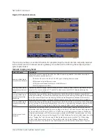
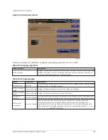
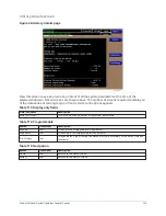
Figure 42: Operations screen
This screen allows the definition of general operating parameters for the chiller.
Table 101: Display only fields
Field/LED name
Description
Chiller run time
Displays the amount of time the chiller has been running since the last start signal was
received. The value is reset to zero when the chiller enters Coastdown. It remains at
zero while shut down and during “System Prelube”.
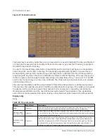
Table 102: Programmable
Button
Access level
Description
Control source
Operator
Defines whether the control of the chiller will be Local, Digital Remote, Analog Remote,
Modem Remote, or ISN (BAS) Remote.
Chiller number of
starts
Admin to change Displays the total number of the starts the chiller has initiated.
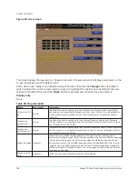
Chiller operating
hours
Admin to change Displays the total accumulated run time of the chiller.
Edit phone
numbers
Service to change The Local service phone number is displayed as the second number. Although blank
by default, the appropriate label and number can be entered by a Service Technician.
Chiller style/
compressor
Service to change
Used to enter the chiller style/compressor combination. Once the chiller style/
compressor combination is entered, the program controls the chiller per the
requirements of the entered chiller and compressor. The selection determines the
minimum (default) allowable coastdown duration programmable with the
Coastdown
Time Setpoint
on the SETUP Screen.
105
Model YD Mod D with OptiView Control Center
Summary of Contents for YD Mod D
Page 2: ...2 Model YD Mod D with OptiView Control Center...
Page 8: ...Nomenclature Model YD Mod D with OptiView Control Center 8...
Page 17: ...Figure 2 Chiller operation flow chart 17 Model YD Mod D with OptiView Control Center...
Page 18: ...Figure 2 Chiller operation flow chart Model YD Mod D with OptiView Control Center 18...
Page 19: ...Figure 2 Chiller operation flow chart 19 Model YD Mod D with OptiView Control Center...
Page 20: ...Figure 2 Chiller operation flow chart Model YD Mod D with OptiView Control Center 20...
Page 21: ...Figure 2 Chiller operation flow chart 21 Model YD Mod D with OptiView Control Center...
Page 22: ...Figure 2 Chiller operation flow chart Model YD Mod D with OptiView Control Center 22...
Page 150: ...Figure 57 Sample printout status Model YD Mod D with OptiView Control Center 150...
Page 151: ...Figure 57 Sample printout status 151 Model YD Mod D with OptiView Control Center...
Page 152: ...Figure 58 Sample printout setpoints Model YD Mod D with OptiView Control Center 152...
Page 153: ...Figure 58 Sample printout setpoints 153 Model YD Mod D with OptiView Control Center...
Page 154: ...Figure 59 Sample printout schedule Model YD Mod D with OptiView Control Center 154...
Page 155: ...Figure 60 Sample printout sales order 155 Model YD Mod D with OptiView Control Center...
Page 156: ...Figure 61 Sample printout history Model YD Mod D with OptiView Control Center 156...
Page 157: ...Figure 61 Sample printout history 157 Model YD Mod D with OptiView Control Center...
Page 159: ...Figure 64 Sample printout custom screen report 159 Model YD Mod D with OptiView Control Center...