


Advanced trend setup screen
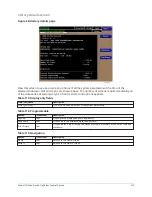
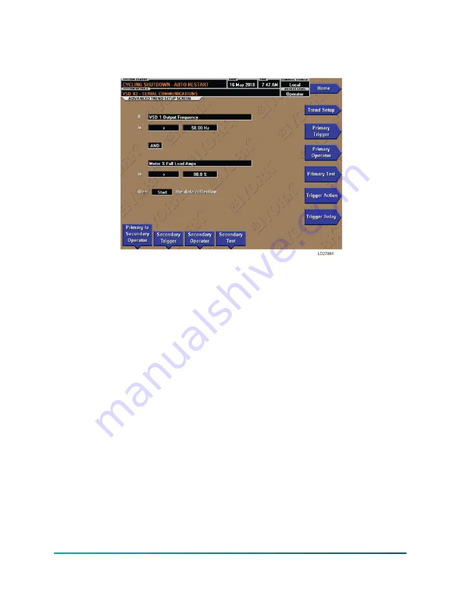
Figure 53: Advanced trend setup screen
The desired data collection start/stop triggers are setup on this screen. The trend data collection
can be set to start or stop based upon the status of up to two selected triggers. The triggers can
consist of digital events or analog parameters compared to thresholds. The triggers can be used
individually or in combination. The digital and analog parameters are selected from the Common
slots screen (or Master slot numbers list).
The parameter selected as the Primary Trigger is compared to a value selected as the Primary Test,
using the Primary Operator as a comparator. If it is evaluated as true, then the data collection is
started or stopped (after any selected Trigger delay) per the selected Trigger Action.
A Secondary Trigger can be evaluated with the Primary Trigger to start/stop data collection. The
Primary to Secondary Operator is used to define the trigger combinations required to be true to
start/stop data collection. The Secondary Trigger is setup and evaluated the same as the Primary
Trigger.
Entry fields are as follows:
•
If
Primary Trigger
•
is
Primary Operator
Primary Test
•
Primary to Secondary Operator
to
Secondary Operator
•
Secondary Trigger
•
is
Secondary Operator
Secondary Test
•
then
Trigger Action
the data collection
•
with a delay of
Trigger Delay
After the required triggers are set, the
Start
key on the Trend screen must be manually pressed
before the triggers will be evaluated. While waiting for the triggers to start or stop data collection,
a status message is displayed in the upper right corner of the Trend screen describing the pending
action.
Model YD Mod D with OptiView Control Center
122
Summary of Contents for YD Mod D
Page 2: ...2 Model YD Mod D with OptiView Control Center...
Page 8: ...Nomenclature Model YD Mod D with OptiView Control Center 8...
Page 17: ...Figure 2 Chiller operation flow chart 17 Model YD Mod D with OptiView Control Center...
Page 18: ...Figure 2 Chiller operation flow chart Model YD Mod D with OptiView Control Center 18...
Page 19: ...Figure 2 Chiller operation flow chart 19 Model YD Mod D with OptiView Control Center...
Page 20: ...Figure 2 Chiller operation flow chart Model YD Mod D with OptiView Control Center 20...
Page 21: ...Figure 2 Chiller operation flow chart 21 Model YD Mod D with OptiView Control Center...
Page 22: ...Figure 2 Chiller operation flow chart Model YD Mod D with OptiView Control Center 22...
Page 150: ...Figure 57 Sample printout status Model YD Mod D with OptiView Control Center 150...
Page 151: ...Figure 57 Sample printout status 151 Model YD Mod D with OptiView Control Center...
Page 152: ...Figure 58 Sample printout setpoints Model YD Mod D with OptiView Control Center 152...
Page 153: ...Figure 58 Sample printout setpoints 153 Model YD Mod D with OptiView Control Center...
Page 154: ...Figure 59 Sample printout schedule Model YD Mod D with OptiView Control Center 154...
Page 155: ...Figure 60 Sample printout sales order 155 Model YD Mod D with OptiView Control Center...
Page 156: ...Figure 61 Sample printout history Model YD Mod D with OptiView Control Center 156...
Page 157: ...Figure 61 Sample printout history 157 Model YD Mod D with OptiView Control Center...
Page 159: ...Figure 64 Sample printout custom screen report 159 Model YD Mod D with OptiView Control Center...