


FORM 150.65-NM4
81
YORK INTERNATIONAL
SYSTEM START-UP CHECKLIST
CHECKING THE SYSTEM 24 HOURS PRIOR TO
INITIAL START-UP (NO POWER)
JOB NAME: __________________________________
SALES
ORDER #: ___________________________________
LOCATION: __________________________________
SOLD BY: ___________________________________
INSTALLING
CONTRACTOR: ______________________________
STARTUP: ___________________________________
TECHNICIAN/
COMPANY: __________________________________
DATE: ______________________________________
CHILLER
MODEL #: _________________________________
SERIAL #: _________________________________
COMPRESSOR #1
MODEL #: _________________________________
SERIAL #: _________________________________
COMPRESSOR #2
MODEL #: _________________________________
SERIAL #: _________________________________
Unit Checks
'
1. Inspect the unit for shipping or installation dam-
age.
'
2. Assure that all piping has been completed.
'
3. Check that the unit is properly charged and
that there are no piping leaks.
'
4. Suction and discharge stop valves and the re-
frigerant liquid stop valves are open (ccw).
CAUTION: Compressor lubrication circuit must be
primed with YORK “C” oil prior to start-up.
Priming should be done through the
Schrader fitting at the compressor oil pump.
Stroke oil pump 10 times to prime the lubri-
cation circuit.
'
5. The compressor oil level must be maintained
between the middle of the upper and middle of
the lower sight glass at all operating condi-
tions. At part load operating conditions, it is
not abnormal for the oil level to be in the lower
sight glass. If it is necessary to add oil, con-
nect a YORK oil pump to the oil charging valve,
but do not tighten the flare nut on the delivery
tubing. With the bottom (suction end) of the
pump submerged in oil to avoid the entrance of
air, operate the pump until oil drips from the
flare nut joint, allowing the air to be expelled,
and tighten the flare nut. Open the compres-
sor oil charging valve and pump in oil until the
oil reaches the proper level as described above.
Close the compressor oil charging valve.
'
6. Assure water pumps are on. Check and adjust
water pump flow rate and pressure drop across
cooler.
'
7. Check panel to see that it is free of foreign
material (wires, metal chips, etc.).
'
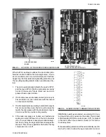
8. Visually inspect wiring (power & control). Must
meet NEC and all local codes.
(See Fig. 10 & 12)
'
9. Check for proper size fuses in main and con-
trol power circuits.
'
10. Verify that field wiring matches the 3-phase
power requirements of the compressor. See
nameplate. (See Fig. 10)
'
11. Assure 115VAC Control Power to TB1 has 30A
minimum capacity. (See Fig. 10)
'
12. Be certain all control bulbs are inserted com-
pletely in their respective wells and are coated
with heat conductive compound.
PANEL CHECKS (POWER ON, BOTH SYSTEM
SWITCHES “OFF”)
'
1. Apply 3-phase power and verify its value. (See
Fig. 10).
φ
A: ____,
φ
B: ____,
φ
C: ____ VAC
'
2. Apply 115VAC and verify its value on the termi-
nal block in the lower left of the Power Panel.
Make the measurement between terminals 5
and 2. Should be 115VAC ± 10%. (See Fig.
10). ______ VAC
'
3. Assure crankcase heaters are on. Allow crank-
case heaters to remain on a minimum of 24
Summary of Contents for Millennium YCAJ150
Page 21: ...FORM 150 65 NM4 21 YORK INTERNATIONAL LD02461 FIG 6 ELEMENTARY DIAGRAM Cont d...
Page 22: ...22 YORK INTERNATIONAL ELEMENTARY DIAGRAM...
Page 24: ...24 YORK INTERNATIONAL CONNECTION DIAGRAM FIG 7 CONNECTION DIAGRAM LD02463...
Page 25: ...FORM 150 65 NM4 25 YORK INTERNATIONAL FIG 7 CONNECTION DIAGRAM Cont d LD02462...
Page 30: ...30 YORK INTERNATIONAL FIG 8 SYSTEM WIRING Cont d LD02499...
Page 100: ...100 YORK INTERNATIONAL LD02654 FIG 37B LOUVER BRACKETS INSTALLATION...
Page 103: ...FORM 150 65 NM4 103 YORK INTERNATIONAL LD02656 FIG 39A LOUVER INSTALLATION SIDES...
Page 104: ...104 YORK INTERNATIONAL LD02654 FIG 39B LOUVER BRACKETS INSTALLATION...
Page 108: ...108 YORK INTERNATIONAL FIG 40B CONDENSER COIL LOUVER INSTALLATION FRONT AND BACK LD02659...
Page 110: ...110 YORK INTERNATIONAL FIG 41 REMOTE RESET BOARD LD02666 P1...