


FORM 150.65-NM4
17
YORK INTERNATIONAL
25112A
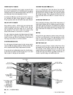
FIG. 5 – COMPRESSOR MOUNTING PAD
COMPRESSOR MOUNTING PAD
INSPECTION
Immediately upon receiving the unit, it should be in-
spected for possible damage which may have occurred
during transit. If damage is evident, it should be noted on
the carrier’s freight bill. A written request for inspection
by the carrier’s agent should be made at once. See In-
struction 50.15-NM for more information and details.
LOCATION AND CLEARANCES
These units are designed for outdoor installations on
ground level, rooftop, or beside a building. The location
should be selected for minimum sun exposure and to
insure an adequate supply of fresh air for the condenser.
The units must be installed with sufficient clearances for
air entrance to the condenser coil, for air discharge away
from the condenser, and for servicing access.
In installations where winter operation is intended and
snow accumulations are expected, additional height must
be provided to insure normal condenser air flow. (See
DIMENSIONS pages 10 and 11).
FOUNDATION
The unit should be mounted on a flat and level founda-
tion, floor or rooftop, capable of supporting the entire
operating weight of the equipment. See PHYSICAL DATA
pages 8 and 9 for operating weight. If the unit is elevated
beyond the normal reach of service personnel, a suit-
able catwalk must be constructed around the unit. The
catwalk must be capable of supporting service person-
nel, their equipment, and the reciprocating compressors.
Ground Level Locations
It is important that the units be installed on a substantial
base that will not settle. A one piece concrete slab with
footers extended below the frost line is highly recom-
mended. Additionally, the slab should not be tied to the
main building foundation as noise and vibration may be
transmitted.
Mounting holes are provided in the steel channel for bolt-
ing the unit to its foundation. (See DIMENSIONS pages
10 and 11).
For ground level installations, precautions should be taken
to protect the unit from tampering by or injury to unau-
thorized persons. Screws and/or latches on access pan-
els will prevent casual tampering. However, further safety
precautions such as a fenced-in enclosure or locking
devices on the panels may be advisable. A tamperproof
kit is available as an option. Check local authorities for
safety regulations.
Rooftop Locations
Choose a spot with adequate structural strength to safely
support the entire weight of the unit and service person-
nel. Care must be taken not to damage the roof.
Consult the building contractor or architect if the roof is
bonded. Roof installations should have wooden beams
(treated to reduce deterioration), cork, rubber or vibra-
tion isolators under the base to minimize vibration.
SHIPPING BRACES
Two shipping brackets (typically galvanized steel) which
run diagonally along each side of the unit, must be re-
moved once the unit is mounted on its foundation. A
third bracket on the right rear of the unit should also be
removed. This bracket runs across the bottom right cor-
ner of the unit behind the compressors.
SPRING ISOLATORS (OPTIONAL)
When ordered, eight (8) spring isolators will be furnished.
1. Identify isolator and locate at proper mounting point
using table on page 18.
2. Block up equipment so as to install spring mounts
with pin on top of housing into Equipment Mounting
Holes.
3. Mounting Adjust Nut is inside the isolator mount lo-
cated just below the top plate of the mount. Turn nut
2 turns clockwise (down) to load spring mount at each
location.
4. Take two additional turns on Adjustment Nut of each
location.
5. Repeat step No. 3 as many times as necessary to
bring height of isolator to proper height.
6. Take additional turns on mounts at low side or corner
to level the equipment.
COMPRESSOR MOUNTING
The compressors are mounted on four (4) isolator pads
(one under each compressor foot). (See Fig. 5). The mount-
ing bolts are not to be loosened or adjusted at installation.
Summary of Contents for Millennium YCAJ150
Page 21: ...FORM 150 65 NM4 21 YORK INTERNATIONAL LD02461 FIG 6 ELEMENTARY DIAGRAM Cont d...
Page 22: ...22 YORK INTERNATIONAL ELEMENTARY DIAGRAM...
Page 24: ...24 YORK INTERNATIONAL CONNECTION DIAGRAM FIG 7 CONNECTION DIAGRAM LD02463...
Page 25: ...FORM 150 65 NM4 25 YORK INTERNATIONAL FIG 7 CONNECTION DIAGRAM Cont d LD02462...
Page 30: ...30 YORK INTERNATIONAL FIG 8 SYSTEM WIRING Cont d LD02499...
Page 100: ...100 YORK INTERNATIONAL LD02654 FIG 37B LOUVER BRACKETS INSTALLATION...
Page 103: ...FORM 150 65 NM4 103 YORK INTERNATIONAL LD02656 FIG 39A LOUVER INSTALLATION SIDES...
Page 104: ...104 YORK INTERNATIONAL LD02654 FIG 39B LOUVER BRACKETS INSTALLATION...
Page 108: ...108 YORK INTERNATIONAL FIG 40B CONDENSER COIL LOUVER INSTALLATION FRONT AND BACK LD02659...
Page 110: ...110 YORK INTERNATIONAL FIG 41 REMOTE RESET BOARD LD02666 P1...