


FORM 150.65-NM4
61
YORK INTERNATIONAL
Monitoring motor current assures that motor life is not
compromised due to low motor current. Low motor cur-
rent may be caused by loss or low voltage on the high
voltage supply which could quickly result in motor fail-
ure. Low motor current may also result from low refriger-
ant charge. This assures that the compressor does not
run with a low suction pressure condition while the low
pressure bypass is de-activated.
The micro begins monitoring for low motor current 4 sec-
onds after a compressor starts. If after 4 seconds the
motor current drops below 15% FLA, the micro will shut
the compressor down.
NOTE: Do not confuse FLA and RLA. FLA (full-load
amps) is approximately 1.2 x RLA. RLA (run-
ning load amps) specified on the motor name-
plate is typical current demand under rated op-
erating conditions in a fully loaded system. There-
fore, do not expect to see 100% FLA when the
system is fully loaded. In this condition, cur-
rents may run approximately 65 - 85% FLA.
Three internal temperature sensors are built into the motor
stator. These sensors are wired into the motor protector
module located inside the motor terminal box. As the
motor windings heat and cool, the resistance of the mo-
tor temperature sensors will change. If the windings over-
heat, the change in resistance in the sensors will be
sensed by the motor protector module. The module will
open its MP contacts breaking the 115VAC fed to the
motor contactor. When the motor contactor de-energizes,
motor current falls to zero. The low motor current is
sensed by the microprocessor and the system is shut
down.
Once tripped, the Motor Protector Module will not reset
unless power (115VAC) is removed for at least 5 sec-
onds from the control panel. Therefore, after 2 more start
attempts, the micro will lock out on a low motor current
safety and also requires 115VAC control power to be
removed and reapplied along with manual reset via the
system switch.
A mechanical high pressure cut-out is located on each
compressor discharge or in the compressor head. This
is the primary high pressure safety in the system. Any
microprocessor controls are secondary.
Anytime discharge pressure exceeds 405 PSIG (2.8
mPa), the contacts in the high pressure cut-out will open
which removes 115VAC from the motor protector mod-
ule. When 115VAC control power is lost to the module,
the module’s MP contacts open breaking the 115VAC
fed to the motor contactor. The motor contactor de-ener-
gizes and motor current falls to zero. The low motor cur-
rent is sensed by the microprocessor and the system is
There are three types of System Safeties: The Manual
Reset type, the Automatic Reset type, and Anticipation
Safety Controls. These safeties protect the chiller from
damage anytime a safety threshold is exceeded by ei-
ther shutting the system(s) down or by altering system
loading. Continuous monitoring by the microprocessor
assures that instantaneous reactions result. A status
display message will indicate when a system(s) or the
entire chiller is shut down due to a fault or when Antici-
pation safeties are operating.
An explanation of these safeties will follow.
MANUAL RESET SAFETIES (3 Faults and Lockout)
A Manual Reset Safety will shut the affected system
down whenever the safety threshold is exceeded. Auto-
matic restart will occur after the first 2 shutdowns when
the anti-recycle timer times out, if temperature demand
exists. After any combination of 3 Manual Reset Safe-
ties in a 90-minute time period, the affected system will
shut down and lock out on a FAULT.
After a system has shut down 3 times and locked out, a
fault display indicating the last system fault will appear
on the STATUS display message. This is accessible by
pressing the STATUS key.
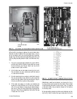
To reset a locked out system, turn the affected system
switch on the Microprocessor Board (Page 74) to the
OFF position.
CAUTION: Before returning a locked out system to
service, a thorough investigation of the cause
of the fault should be made. Failure to re-
pair the cause of the fault while manually
allowing repetitive restarts may cause fur-
ther expensive damage to the system.
Each of the Manual Reset Safeties will be discussed in
detail below.
MOTOR CURRENT
(Low Motor Current, Motor Protector, and
Mechanical High Pressure Cutout Safety)
This safety combines several safeties into one. The mi-
cro monitors for low motor current as sensed by the C.T.,
the mechanical motor protector, and the high pressure
cutout.
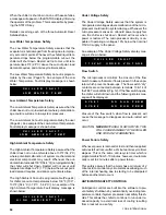
An example of the fault display is shown below:
“SYSTEM SAFETIES”
S Y S # 1
M O T O R
C U R R E N T
S Y S # 2
M O T O R
C U R R E N T
Summary of Contents for Millennium YCAJ150
Page 21: ...FORM 150 65 NM4 21 YORK INTERNATIONAL LD02461 FIG 6 ELEMENTARY DIAGRAM Cont d...
Page 22: ...22 YORK INTERNATIONAL ELEMENTARY DIAGRAM...
Page 24: ...24 YORK INTERNATIONAL CONNECTION DIAGRAM FIG 7 CONNECTION DIAGRAM LD02463...
Page 25: ...FORM 150 65 NM4 25 YORK INTERNATIONAL FIG 7 CONNECTION DIAGRAM Cont d LD02462...
Page 30: ...30 YORK INTERNATIONAL FIG 8 SYSTEM WIRING Cont d LD02499...
Page 100: ...100 YORK INTERNATIONAL LD02654 FIG 37B LOUVER BRACKETS INSTALLATION...
Page 103: ...FORM 150 65 NM4 103 YORK INTERNATIONAL LD02656 FIG 39A LOUVER INSTALLATION SIDES...
Page 104: ...104 YORK INTERNATIONAL LD02654 FIG 39B LOUVER BRACKETS INSTALLATION...
Page 108: ...108 YORK INTERNATIONAL FIG 40B CONDENSER COIL LOUVER INSTALLATION FRONT AND BACK LD02659...
Page 110: ...110 YORK INTERNATIONAL FIG 41 REMOTE RESET BOARD LD02666 P1...