


FORM 150.65-NM4
75
YORK INTERNATIONAL
26000A
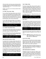
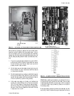
FIG. 23 – LOCATION OF THE MICROPROCESSOR BOARD
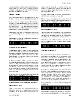
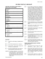
FIG. 24 – ALARM CONTACT CONNECTION LOCATION
LD02092
26001A
SYSTEM SWITCHES 1-4
ON MICROPROCESSOR BOARD
MICROPROCESSOR
BOARD
When AUTO Lead/Lag is utilized, the micro attempts to
balance run time between the two compressors. A num-
ber of conditions can occur which will prevent this from
happening. Factors determining lead/lag selection and
the resulting lead/lag determination are discussed be-
low:
1.
The micro automatically defaults the lead to SYS 1
and the lag to SYS 2 if both compressors are ready
to start (Anti-recycle Timers timed out) and com-
pressors have equal run time.
2.
If both compressors are ready to start (Anti-recycle
Timers timed out), the compressor with the lowest
run hours will start first.
3.
If both compressors are waiting to start (Anti-recycle
Timers are not timed out), the micro will assign the
lead to the compressor with the shortest anti-recycle
time in an effort to provide cooling quickly.
4.
If the lead compressor is locked out, faulted and
waiting to restart, SYS switch on the micro board is
off, or a run permissive is keeping an individual sys-
tem from running, the lag compressor is swapped to
the lead. This is true regardless of whether the lag
compressor is on or off.
If MANUAL Lead/Lag is selected, an external “dry” con-
tact (switch) must be wired into the chiller. This contact
is field supplied. With the contact open, SYS 1 is placed
in the lead. When the contact is closed, SYS 2 will be
the lead system.
Manual Lead/Lag selection will be automatically overrid-
den by the micro to allow the lag compressor in a mod-
Summary of Contents for Millennium YCAJ150
Page 21: ...FORM 150 65 NM4 21 YORK INTERNATIONAL LD02461 FIG 6 ELEMENTARY DIAGRAM Cont d...
Page 22: ...22 YORK INTERNATIONAL ELEMENTARY DIAGRAM...
Page 24: ...24 YORK INTERNATIONAL CONNECTION DIAGRAM FIG 7 CONNECTION DIAGRAM LD02463...
Page 25: ...FORM 150 65 NM4 25 YORK INTERNATIONAL FIG 7 CONNECTION DIAGRAM Cont d LD02462...
Page 30: ...30 YORK INTERNATIONAL FIG 8 SYSTEM WIRING Cont d LD02499...
Page 100: ...100 YORK INTERNATIONAL LD02654 FIG 37B LOUVER BRACKETS INSTALLATION...
Page 103: ...FORM 150 65 NM4 103 YORK INTERNATIONAL LD02656 FIG 39A LOUVER INSTALLATION SIDES...
Page 104: ...104 YORK INTERNATIONAL LD02654 FIG 39B LOUVER BRACKETS INSTALLATION...
Page 108: ...108 YORK INTERNATIONAL FIG 40B CONDENSER COIL LOUVER INSTALLATION FRONT AND BACK LD02659...
Page 110: ...110 YORK INTERNATIONAL FIG 41 REMOTE RESET BOARD LD02666 P1...