


FORM 150.65-NM4
113
YORK INTERNATIONAL
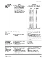
“Chiller Fault: Low
3. Defective LWT or RWT sensor.
3. Check according to following table (use
Water Temp”
(Assure the sensor is properly in-
digital volt meter)*. Replace if necessary.
(Cont’d)
stalled in the bottom of the well
with a generous amount of heat
TEMP.
VOLTAGE (DC)
conductive compound.
20.0°F (11.1°C)
1.65
NOTE: It is not unusual to find up
22.0°F (12.2°C)
1.71
to a +/–2°F (1.1°C) difference
25.0°F (13.9°C)
1.82
between the display and a thermo-
27.0°F (15.0°C)
1.88
meter located in water piping.
30.0°F (16.7°C)
1.99
33.0°F (18.3°C)
2.09
36.0°F (20.0°C)
2.22
38.0°F (21.1°C)
2.28
41.0°F (22.8°C)
2.37
43.0°F (23.9°C)
2.43
46.0°F (25.6°C)
2.54
48.0°F (26.7°C)
2.60
50.0°F (27.8°C)
2.67
53.0°F (29.4°C)
2.77
55.0°F (30.6°C)
2.83
57.0°F (31.7°C)
2.89
59.0°F (32.8°C)
2.95
61.0°F (33.9°C)
3.02
63.0°F (35.0°C)
3.08
65.0°F (36.1°C)
3.14
67.0°F (37.2°C)
3.20
70.0°F (38.9°C)
3.28
* Check voltage on Microprocessor Board.
LWT: J11-7 to J11-1
RWT: J11-8 to J11-1
Low Compressor Oil
1. Low oil charge.
1. Oil level should be visible in either sight
Level
glass at all times. Add YORK “C” oil if
(Particularly at
necessary.
start-up)
2. Excessive flood back of liquid
2. Adjust Thermal Expansion Valve (TXV) or
refrigerant.
replace power element. Check TXV bulb
location. Should be located on suction line
at least 8" - 10" from nearest elbow. Bulb
should be at 4 o’clock or 8 o’clock position,
have good contact with suction line and be
well insulated.
Crankcase Heater
1. Open at 115VAC wiring to heater.
1. Check wiring.
won’t Energize
2. Defective heater.
2. Replace heater.
(Should energize any-
3. Auxiliary contacts of compressor
3. Replace contactor.
time unit is “OFF”)
contactor defective.
(Min. current draw = 2
amps)
Compressor won’t
1. Suction pressure > programmed un-
1. Excessive load. Check OPERATING LIMI-
load
load point or operating limitations
TATIONS. Check programmed unloading
(Solenoid valve de-
have been exceeded.
point.
energizes to load
2. Discharge pressure > programmed
2. Check OPERATING LIMITATIONS.
compressor)
unload point or operating limitations
Check programmed unloading point.
have been exceeded.
3. Demand not great enough.
3. OK. Become familiar with control operation.
4. Defective loading solenoid.
4. Replace compressor loading solenoid.
PROBLEM
CAUSE
SOLUTION
Summary of Contents for Millennium YCAJ150
Page 21: ...FORM 150 65 NM4 21 YORK INTERNATIONAL LD02461 FIG 6 ELEMENTARY DIAGRAM Cont d...
Page 22: ...22 YORK INTERNATIONAL ELEMENTARY DIAGRAM...
Page 24: ...24 YORK INTERNATIONAL CONNECTION DIAGRAM FIG 7 CONNECTION DIAGRAM LD02463...
Page 25: ...FORM 150 65 NM4 25 YORK INTERNATIONAL FIG 7 CONNECTION DIAGRAM Cont d LD02462...
Page 30: ...30 YORK INTERNATIONAL FIG 8 SYSTEM WIRING Cont d LD02499...
Page 100: ...100 YORK INTERNATIONAL LD02654 FIG 37B LOUVER BRACKETS INSTALLATION...
Page 103: ...FORM 150 65 NM4 103 YORK INTERNATIONAL LD02656 FIG 39A LOUVER INSTALLATION SIDES...
Page 104: ...104 YORK INTERNATIONAL LD02654 FIG 39B LOUVER BRACKETS INSTALLATION...
Page 108: ...108 YORK INTERNATIONAL FIG 40B CONDENSER COIL LOUVER INSTALLATION FRONT AND BACK LD02659...
Page 110: ...110 YORK INTERNATIONAL FIG 41 REMOTE RESET BOARD LD02666 P1...