


40
YORK INTERNATIONAL
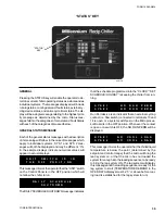
The COMP RUNNING message indicates that the re-
spective compressor is running due to demand.
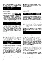
The anti-recycle timer message shows the amount of
time left on the respective anti-recycle timer. This mes-
sage is displayed when demand requires the respective
system to start but is being held off due to the timer.
The anti-coincident timer is a software feature that guards
against 2 compressors starting simultaneously. This as-
sures instantaneous starting current does not become
excessively high due to simultaneous starts. The micro
limits the time between compressor starts to 1 minute
regardless of demand of the anti-recycle timer being timed
out. The time shown on the anti-coincident timer is the
time left on the timer before the respective system will
start. Demand must be present for the message to be
displayed and will only appear when the anti-recycle timer
has timed out.
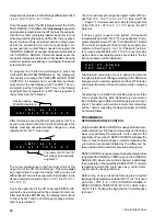
This display informs the operator that the micro is limit-
ing the loading of the system based on motor current.
By programming the AVERAGE CURR UNLOAD point,
the micro will limit the loading of the compressor when-
ever motor current rises above the programmed value.
This feature reduces the chance of a system faulting on
high motor current, motor protector due to motor over-
heating, or high discharge pressure which causes high
motor current. The feature also assures that motor life is
not compromised. Typically, the AVERAGE CURR UN-
LOAD is programmed for 100% to assure that the com-
pressor is allowed to load to its rated FLA.
Discharge Pressure Limiting takes affect when discharge
pressure nears the point at which the high pressure cut-
out will shut the system down causing total loss of cool-
ing. When this message appears, discharge pressure
has exceeded the user programmable threshold and the
micro is unloading the affected system to prevent shut-
down on a manual high pressure cut-out. Reloading will
take place when discharge pressure has dropped 60 PSIG
(4.1 bar) below the threshold.
Optional discharge pressure transducers must be in-
stalled for this feature to operate. This is accomplished
by adding the Discharge Pressure Readout option.
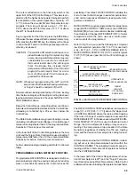
The PUMPING DOWN message indicates that the re-
spective compressor is presently in the process of pump-
ing the system down. The compressor will either be in a
recycling pumpdown or in a pumpdown prior to shut-
down when this message is displayed. The message
will disappear when the compressor shuts off.
If the MANUAL OVERRIDE key is pressed, the STATUS
display will display the message shown above. This will
indicate that the Daily Schedule is being ignored and
the chiller will start-up when water temperature allows,
UNIT Switch permits, and SYSTEM Switches permit.
This is a priority message and cannot be overridden by
anti-recycle messages, fault messages, etc. when in
the STATUS Display mode. Therefore, do not expect to
see any other STATUS messages when in the MANUAL
OVERRIDE mode. MANUAL OVERRIDE is to be used
only in emergencies or for servicing.
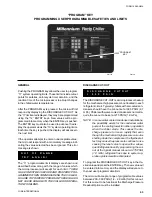
FAULT STATUS MESSAGES
Fourteen possible fault messages may appear when the
STATUS key is pressed. Whenever a fault message ap-
pears, the safety thresholds on the chiller have been
exceeded and the entire chiller or a single system will
be shut down and locked out. A detailed explanation of
the shutdown thresholds and associated information re-
lated to each fault is covered in the SYSTEM SAFETIES
section (Page 61).
Chiller shutdown faults will shut the entire chiller down
and lock it out, while system shutdown faults will only
shut down and lock out the affected system (compres-
sor).
A list of the fault messages are shown on the next page:
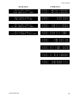
S Y S # 1
A R
T M R
X X X
S
S Y S # 2
A R
T M R
X X X
S
S Y S # 1
A C
T M R
X X
S
S Y S # 2
A C
T M R
X X
S
S Y S # 1
C R N T
L I M I T I N G
S Y S # 2
C R N T
L I M I T I N G
S Y S # 1
P U M P I N G
D O W N
S Y S # 2
P U M P I N G
D O W N
M A N U A L
O V E R R I D E
S Y S # 1
D S C H
L I M I T I N G
S Y S # 2
D S C H
L I M I T I N G
S Y S # 1
C O M P
R U N N I N G
S Y S # 2
C O M P
R U N N I N G
Summary of Contents for Millennium YCAJ150
Page 21: ...FORM 150 65 NM4 21 YORK INTERNATIONAL LD02461 FIG 6 ELEMENTARY DIAGRAM Cont d...
Page 22: ...22 YORK INTERNATIONAL ELEMENTARY DIAGRAM...
Page 24: ...24 YORK INTERNATIONAL CONNECTION DIAGRAM FIG 7 CONNECTION DIAGRAM LD02463...
Page 25: ...FORM 150 65 NM4 25 YORK INTERNATIONAL FIG 7 CONNECTION DIAGRAM Cont d LD02462...
Page 30: ...30 YORK INTERNATIONAL FIG 8 SYSTEM WIRING Cont d LD02499...
Page 100: ...100 YORK INTERNATIONAL LD02654 FIG 37B LOUVER BRACKETS INSTALLATION...
Page 103: ...FORM 150 65 NM4 103 YORK INTERNATIONAL LD02656 FIG 39A LOUVER INSTALLATION SIDES...
Page 104: ...104 YORK INTERNATIONAL LD02654 FIG 39B LOUVER BRACKETS INSTALLATION...
Page 108: ...108 YORK INTERNATIONAL FIG 40B CONDENSER COIL LOUVER INSTALLATION FRONT AND BACK LD02659...
Page 110: ...110 YORK INTERNATIONAL FIG 41 REMOTE RESET BOARD LD02666 P1...