


FORM 150.65-NM4
37
YORK INTERNATIONAL
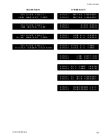
SWITCH 4
OPEN:
Chiller control will be from return water temperature.
CLOSED:
Chiller control will be from leaving water temperature.
SWITCH 5
OPEN:
Display messages will show units of measure in English
units (°F, PSI, etc.).
CLOSED:
Display messages will show units of measure in Metric
units (°C, kPa, etc.).
SWITCH 6
OPEN:
This MUST be selected for chillers with “4” or more
fans where each refrigerant system will have fans
of its own.
CLOSED:
This MUST be selected for “2” fan chillers where
fans are shared by both refrigerant circuits.
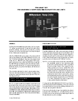
SWITCH 1
OPEN:
The chilled liquid temperature setpoint can only be pro-
grammed from 40 - 70°F* (4.4 - 21.1°C).*
CLOSED:
The chilled liquid temperature setpoint can be pro-
grammed from 15 - 70°F* (-9.4 - 21.1°C).*
SWITCH 2
OPEN:
The low ambient cut-out is fixed at 25°F (-3.9°C).
CLOSED:
The low ambient cut-out is programmable from 0 - 50°F
(-17.8 to 10°C). A low ambient kit MUST be installed if
the switch is placed in this position.
SWITCH 3
OPEN:
This mode allows a Remote Control Center or an ISN
panel to only view chiller operating conditions. It will not
allow changes to any chiller controls or setpoints.
CLOSED:
This mode should be selected in typical applications. It
will allow a Remote Control Center or an ISN panel to
not only view chiller operating conditions, but will also
allow the remote panel to change chiller controls and
setpoints.
C O M F O R T
C O O L I N G
R E T U R N
W A T E R
C O N T R O L
B R I N E
&
C O O L I N G
D U T Y
L E A V I N G
W A T E R
C O N T R O L
S T A N D A R D
A M B I E N T
E N G L I S H
U N I T S
R E A D O U T
L O W
A M B I E N T
C O N T R O L
M E T R I C
U N I T S
R E A D O U T
L O C A L
C O N T R O L
M O D E
S T A N D A R D
C O N D E N S E R
F A N
C O N T R O L
R E M O T E
C O N T R O L
M O D E
S H A R E D
C O N D E N S E R
F A N
C O N T R O L
* Positioning of this switch also affects the range of adjustments on the Suction Pressure Cut-out (page 46) and the Low Leaving Water Temp.
Summary of Contents for Millennium YCAJ150
Page 21: ...FORM 150 65 NM4 21 YORK INTERNATIONAL LD02461 FIG 6 ELEMENTARY DIAGRAM Cont d...
Page 22: ...22 YORK INTERNATIONAL ELEMENTARY DIAGRAM...
Page 24: ...24 YORK INTERNATIONAL CONNECTION DIAGRAM FIG 7 CONNECTION DIAGRAM LD02463...
Page 25: ...FORM 150 65 NM4 25 YORK INTERNATIONAL FIG 7 CONNECTION DIAGRAM Cont d LD02462...
Page 30: ...30 YORK INTERNATIONAL FIG 8 SYSTEM WIRING Cont d LD02499...
Page 100: ...100 YORK INTERNATIONAL LD02654 FIG 37B LOUVER BRACKETS INSTALLATION...
Page 103: ...FORM 150 65 NM4 103 YORK INTERNATIONAL LD02656 FIG 39A LOUVER INSTALLATION SIDES...
Page 104: ...104 YORK INTERNATIONAL LD02654 FIG 39B LOUVER BRACKETS INSTALLATION...
Page 108: ...108 YORK INTERNATIONAL FIG 40B CONDENSER COIL LOUVER INSTALLATION FRONT AND BACK LD02659...
Page 110: ...110 YORK INTERNATIONAL FIG 41 REMOTE RESET BOARD LD02666 P1...