


FORM 150.65-NM4
57
YORK INTERNATIONAL
The micro will accept a range of programmable values
between 0.5 - 5.0°F/min (0.3 - 2.8°C).
LOADING AND UNLOADING
RETURN WATER TEMPERATURE CONTROL
In return water temperature control, loading and unload-
ing will take place according to the difference between
the leaving water temperature setpoint and the actual
return water temperature. By programming the CONTROL
RANGE equal to the actual temperature drop across the
evaporator fully loaded, the microprocessor will be able
to maintain the desired leaving water temperature by
controlling off of the return water temperature (RWT).
Simply, the micro will know that the chiller should be
fully loaded when the RWT is equal to the SE
CONTROL RANGE. As the RWT drops, the micro will
unload the chiller which reduces the capacity (tempera-
ture drop across the evaporator). This maintains the leav-
ing water temperature at the desired setpoint.
Normal loading will occur at intervals of 60 seconds,
according to temperatures determined by the formula
below. Loading may be prevented due to the rate control
circuitry. Anytime the return water temperature falls within
the CONTROL RANGE or the RATE CONTROL RANGE,
RATE CONTROL is in effect and loading may be pre-
vented, if water temperature changes faster than the rate
sensitivity. Loading will never occur in intervals faster
than 60 sec. under any circumstances. This prevents
cycling of the compressors and loaders.
Unloading occurs on temperature drop at temperatures
determined by the formula below. Internal timers have no
effect on unloading.
The micro is capable of providing 5, 7, or 10 steps of
loading/unloading. The chiller MUST be programmed for
the number of steps which were ordered. Otherwise,
improper operation and water temperature control prob-
lems will result.
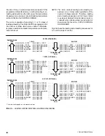
The temperature between stages of loading/unloading is
equal to the CONTROL RANGE divided by the number
of stages. For example:
CONTROL RANGE= 10°F (5.5°C)
Number of Stages = 5
10°F
5 = 2°F (5.5°C
5 = 1.1°C) between stages
In this example, the micro will add a stage of loading
each time the return water temperature rises 2°F
(1.1°C) assuming loading timers and rate control soft-
ware allows.
The micro will unload a stage 2°F (1.1°C) below the
temperature at which it was loaded assuming unload-
ing timers and rate control software allows.
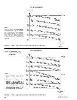
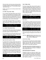
Listed in Fig. 17 - 19 are the loading and unloading se-
quences for 5, 7, and 10 steps of control. A typical
setpoint of 45°F (7.2°C) with a cooling range of 10°F
(5.5°C) is shown for example purposes. The chiller will
be completely loaded at a return water temperature of
55°F (12.8°C) and will be completely off at a tempera-
ture of 45°F (7.2°C), thus maintaining a leaving water
temperature of 45°F (7.2°C). As mentioned before, load-
ing/unloading timers as well as rate control software must
be satisfied before loading/unloading will occur. This re-
duces the possibility of cycling.
LOADING AND UNLOADING
LEAVING WATER TEMPERATURE CONTROL
In leaving water temperature control, loading and unload-
ing will take place as needed to keep water temperature
in the CONTROL RANGE between the TARGET and LOW
LIMIT WATER TEMPERATURE. As mentioned earlier in
this manual, the CONTROL RANGE is the temperature
range of leaving water temperature that is acceptable to
the user and has been previously programmed into
memory using the CHILLED LIQUID TEMP RANGE KEY.
Usually this is a window of water temperatures of about
2 - 3°F (1.1 - 1.7°C). The micro will cause loading and
unloading actions to occur as needed to keep leaving
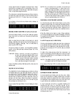
water temperatures in the lower half of this range. Refer
to Fig. 16 to aid in understanding the loading and un-
loading scheme performed by the microprocessor.
Within the lower half of the CONTROL RANGE, the mi-
croprocessor may call for further unloading if the Rate
Sensitivity is exceeded. If temperature drop exceeds 1X
the Rate Sensitivity, the micro will unload the chiller to
prevent overshoot.
Normal unloading will occur if leaving water temperature
should fall into the temperature range “BELOW THE
CONTROL RANGE” which is below the programmed Low
Limit WATER TEMPERATURE. The microprocessor will
unload the chiller in 20 sec. intervals until water tem-
perature rises back into the CONTROL RANGE.
If leaving water temperature rises into the upper half of
CONTROL RANGE or above, the microprocessor will load
the chiIler as needed in 150 sec. intervals until tempera-
tures fall into the lower half of the CONTROL RANGE. If
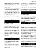
FIG. 16 – LEAVING WATER TEMPERATURE CONTROL
UPPER LIMIT OF
CONTROL RANGE
TARGET
LOW LIMIT WATER
TEMPERATURE
ABOVE THE RATE CONTROL RANGE
RATE CONTROL TEMP RANGE
CONTROL RANGE (CR)
BELOW THE CONTROL RANGE
Summary of Contents for Millennium YCAJ150
Page 21: ...FORM 150 65 NM4 21 YORK INTERNATIONAL LD02461 FIG 6 ELEMENTARY DIAGRAM Cont d...
Page 22: ...22 YORK INTERNATIONAL ELEMENTARY DIAGRAM...
Page 24: ...24 YORK INTERNATIONAL CONNECTION DIAGRAM FIG 7 CONNECTION DIAGRAM LD02463...
Page 25: ...FORM 150 65 NM4 25 YORK INTERNATIONAL FIG 7 CONNECTION DIAGRAM Cont d LD02462...
Page 30: ...30 YORK INTERNATIONAL FIG 8 SYSTEM WIRING Cont d LD02499...
Page 100: ...100 YORK INTERNATIONAL LD02654 FIG 37B LOUVER BRACKETS INSTALLATION...
Page 103: ...FORM 150 65 NM4 103 YORK INTERNATIONAL LD02656 FIG 39A LOUVER INSTALLATION SIDES...
Page 104: ...104 YORK INTERNATIONAL LD02654 FIG 39B LOUVER BRACKETS INSTALLATION...
Page 108: ...108 YORK INTERNATIONAL FIG 40B CONDENSER COIL LOUVER INSTALLATION FRONT AND BACK LD02659...
Page 110: ...110 YORK INTERNATIONAL FIG 41 REMOTE RESET BOARD LD02666 P1...