


FORM 150.65-NM4
55
YORK INTERNATIONAL
The cursor will advance to the final entry which is the
upper limit of the CR (Control Range). This value is pro-
grammed for the highest leaving water temperature which
is acceptable in the system application. Typically, 2°F
(1.1°C) above the Low-Limit Water Temperature is ap-
propriate. The micro will accept a value 1 - 5°F (0.5 -
2.8°C) above the LWT for this value. 2°F (1.1°C) above
the LWT is the default value.
Key in upper limit of the CR and press the ENTER key.
Otherwise the new values will not be entered into memory.
After pressing the ENTER key, the display will continue
to show the LWT and Control Range message until an-
other key is pressed.
CAUTION: Too small of a CR selection will cause com-
pressor/loader cycling. If compressor cycling
occurs, leaving water temperature may vary
considerably as a result of a compressor
that cannot restart due to the anti-recycle
timer. To eliminate this, increase the
∆
T
(temperature differential) of the CR and/or
program the anti-recycle timer for a mini-
mum of 300 seconds if it isn’t already pro-
grammed for 300 seconds.
NOTE: Whenever reprogramming the LWT and CR,
keep in mind that the desired leaving water temp.
or “target” should be midpoint of the CR.
Normal pulldown loading is limited by a 150 sec. loading
timer between stages, with loading occurring whenever
leaving water temperature is in the upper half of the CON-
TROL RANGE or above.
Below the Control Range, unloading will occur at 20 sec.
intervals until temperatures fall back into the Control Zone.
Unloading is controlled by a 20 sec. timer below the
Control Zone.
The Rate Control software may prevent loading or cause
unloading in the Rate Control Range or Control Range if
temperature drops faster than 2X the programmed Rate
Sensitivity. This is to prevent overshoot.
In the lower half of the Control Range between the Low
Limit and the Target, Rate Control will cause unloading if
temperature falls faster than 1X the programmed Rate
Sensitivity. As before, this is to prevent overshoot.
Further details loading/unloading and Rate Control will
follow:
PROGRAMMING LEAVING WATER RATE CONTROL
Programmable RATE CONTROL is designed to limit com-
pressor/loader cycling thus saving energy and reducing
wear on mechanical components. It also reduces the
possibility of “overshoot”. RATE CONTROL will allow the
micro to react to fast changes in water temperature be-
yond normal responses dictated by leaving water tem-
perature and setpoint.
RATE CONTROL requires programming the temperature
range (RATE CONTROL TEMP) above the CONTROL
RANGE (CR) where rate control is desired. Additionally,
the actual rate of change (RATE SENSITIVITY) of water
temperature which the micro uses as a control refer-
ence must also be programmed.
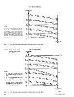
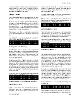
Refer to Fig.15 as you read the following text. A typical
low limit water temperature of 44°F (6.7°C) is used with
a 44 - 46°F (6.7 - 7.8°C) CONTROL RANGE (CR). A
RATE CONTROL TEMP of 10°F (5.5°C), which is typical
(10°F [5.5°C] above upper limit of the Control Range), is
shown.
The RATE CONTROL TEMP establishes a temperature
range (0.1 - 20°F [0.05 - 11.1°C]) above the “Upper Limit
of CONTROL RANGE” where the micro will limit loading
if the rate of change of water temperature exceeds the
RATE SENSITIVITY. In the above example a RATE CON-
TROL TEMP of 10°F (5.5°C) is used. In the Rate Control
Range, the micro will prevent loading or may cause un-
loading if the temperature drop exceeds 2X the Rate
Sensitivity regardless of whether the 150 sec. loading
timer and the deviation from setpoint is calling for load-
ing.
At temperatures below the CONTROL RANGE, unload-
ing will occur to bring temperatures back to within the
CONTROL RANGE. The unloading timer will cause un-
loading at 20 sec. intervals until temperatures fall back
into the CONTROL RANGE.
In the lower half of the Control Range between the Low
Limit Water Setpoint (LWT) and the “Target” Tempera-
ture (Desired Leaving Water Temperature), Rate Control
software will cause unloading if temperature drops faster
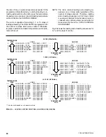
UPPER LIMIT OF RATE
CONTROL TEMP RANGE
UPPER LIMIT OF
CONTROL RANGE (CR)
TARGET
LOW LIMIT
OF CONTROL
RANGE (LWT)
FIG. 15 – LEAVING WATER TEMPERATURE CONTROL
ABOVE THE RATE CONTROL
TEMP RANGE
D
RATE CONTROL TEMP RANGE
(RATE CONTROL TEMP = 10°F [5.5°C])
E
D
CONTROL RANGE
(CR = 44 - 46°F [6.7 - 7.8°C])
E
BELOW THE
CONTROL RANGE
56°
(13.3°)
46°
(7.8°)
45°
(7.2°)
44°
(6.7°)
Summary of Contents for Millennium YCAJ150
Page 21: ...FORM 150 65 NM4 21 YORK INTERNATIONAL LD02461 FIG 6 ELEMENTARY DIAGRAM Cont d...
Page 22: ...22 YORK INTERNATIONAL ELEMENTARY DIAGRAM...
Page 24: ...24 YORK INTERNATIONAL CONNECTION DIAGRAM FIG 7 CONNECTION DIAGRAM LD02463...
Page 25: ...FORM 150 65 NM4 25 YORK INTERNATIONAL FIG 7 CONNECTION DIAGRAM Cont d LD02462...
Page 30: ...30 YORK INTERNATIONAL FIG 8 SYSTEM WIRING Cont d LD02499...
Page 100: ...100 YORK INTERNATIONAL LD02654 FIG 37B LOUVER BRACKETS INSTALLATION...
Page 103: ...FORM 150 65 NM4 103 YORK INTERNATIONAL LD02656 FIG 39A LOUVER INSTALLATION SIDES...
Page 104: ...104 YORK INTERNATIONAL LD02654 FIG 39B LOUVER BRACKETS INSTALLATION...
Page 108: ...108 YORK INTERNATIONAL FIG 40B CONDENSER COIL LOUVER INSTALLATION FRONT AND BACK LD02659...
Page 110: ...110 YORK INTERNATIONAL FIG 41 REMOTE RESET BOARD LD02666 P1...