


52
YORK INTERNATIONAL
The micro will accept a range of programmable LWT val-
ues from 10.0 - 70.0°F (-12.2 - 21.1°C) (See “SWITCH
1”, Page 37). It will also accept a value for the upper limit
of the CR of 4 - 20°F (2.2 - 11.1°C) above the LWT
Setpoint.
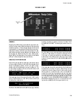
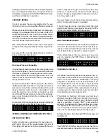
If brine or glycol is used in the system, chilled liquid
temperatures below 40°F (4.4°C) may be desired. To pro-
gram setpoints below 40°F (4.4°C), Dip Switch S1, Switch
#1 on the Microprocessor Board must be properly pro-
grammed. (See Page 36, Fig. 13). If the switch is incor-
rect, when setpoints below 40°F (4.4°C) are entered as
well as when unacceptable values are entered, the fol-
lowing message will be displayed.
Loading and unloading occurs in defined increments
throughout the Control Range according to the difference
between return water temperature and the LWT setpoint.
Loading is limited by a 60 second timer, while unloading
is not.
Loading may be inhibited or unloading may occur if the
micro senses that the Rate Sensitivity is exceeded in
the Control Range or Rate Control Range to prevent over-
shoot. This action will override incremental unloading.
Further details regarding loading/unloading and Rate
Control will follow.
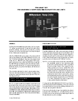
PROGRAMMING
RETURN WATER RATE CONTROL
Programmable RATE CONTROL is designed to limit com-
pressor/loader cycling thus saving energy and reducing
wear on mechanical components. It also reduces the
possibility of “overshoot”. RATE CONTROL will allow the
micro to react to fast changes in water temperature be-
yond normal responses dictated by the difference be-
tween actual return water temperature and setpoint.
RATE CONTROL requires programming the temperature
range (RATE CONTROL TEMP) above the CONTROL
RANGE (CR) where rate control is desired. Additionally,
the actual rate of change (RATE SENSITIVITY) of water
temperature which the micro uses as a control refer-
ence must also be programmed.
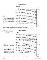
Refer to Fig. 14 as you read the following text. A typical
leaving water temperature setpoint of 45°F (7.2°C) is used
with a 45° - 55°F (7.2 - 12.8°C) CONTROL RANGE. A
RATE CONTROL TEMP OF 65°F (18.3°C), which is typi-
cal (10°F [5.5°C] above the high end the Control Range),
is shown.
temperatures provide a Control Range differential of 54.0
- 44.0 = 10.0°F (12.2 - 6.7 = 5.6°C).
Once the upper limit of the CR is programmed, the “CON-
TROL RANGE” (CR) differential must always equal the
actual water temperature drop (
∆
T) across the evapora-
tor with the chiller completely loaded. Keep this in mind
when programming the high end of the CR. In many cases,
due to improper flows, actual temperature drop occurs
across the evaporator (
∆
T) will not equal design. For
proper operation, adjust flow as needed or program the
“CONTROL RANGE” as needed. However accomplished,
the “CONTROL RANGE” differential must equal the
evaporator temperature drop when fully loaded or leaving
water temperatures well above or well below the desired
setpoint will result.
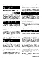
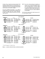
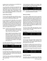
To program the Chilled Liquid Setpoints, press the
CHILLED LIQUID TEMP/RANGE key. The display will
first exhibit a message that “RETURN WATER TEMP
CONTROL” is selected and 3 seconds later automati-
cally scroll to the next display of LWT and CR. The cur-
sor will stop at the first digit of LWT. Key in the “Design
Leaving Water Temperature” (LWT) that is required in
the system. See the following:
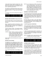
After the Design Leaving Water Temperature (LWT) is
keyed in, the lower limit of the CR (Control Range) in the
display message will automatically change to a value
identical to the “LWT”. See below:
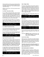
The cursor will advance to the final entry which is the
upper limit of the CR (Control Range). This value must
be programmed to equal the design LWT plus the CR
differential (
∆
T across the evaporator fully loaded). In the
above examples it would be 44.0 + 10.0 = 54.0°F (6.7 +
5.6 = 12.2°C):
Key in the upper limit of the CR and press ENTER. Oth-
erwise the new values will not be entered into memory.
After pressing the ENTER key, the display will continue
to show the LWT and Control Range message until an-
other key is pressed.
O U T
O F
R A N G E
T R Y
A G A I N !
L W T =
4 4 . 0
F
C R =
4 4 . 0
T O
5 4 . 0
F
Design Leaving
Water Temperature
L W T =
4 4 . 0
F
C R =
4 4 . 0
T O
5 4 . 0
F
The lower limit of the CR
will always automatically
equal LWT.
Summary of Contents for Millennium YCAJ150
Page 21: ...FORM 150 65 NM4 21 YORK INTERNATIONAL LD02461 FIG 6 ELEMENTARY DIAGRAM Cont d...
Page 22: ...22 YORK INTERNATIONAL ELEMENTARY DIAGRAM...
Page 24: ...24 YORK INTERNATIONAL CONNECTION DIAGRAM FIG 7 CONNECTION DIAGRAM LD02463...
Page 25: ...FORM 150 65 NM4 25 YORK INTERNATIONAL FIG 7 CONNECTION DIAGRAM Cont d LD02462...
Page 30: ...30 YORK INTERNATIONAL FIG 8 SYSTEM WIRING Cont d LD02499...
Page 100: ...100 YORK INTERNATIONAL LD02654 FIG 37B LOUVER BRACKETS INSTALLATION...
Page 103: ...FORM 150 65 NM4 103 YORK INTERNATIONAL LD02656 FIG 39A LOUVER INSTALLATION SIDES...
Page 104: ...104 YORK INTERNATIONAL LD02654 FIG 39B LOUVER BRACKETS INSTALLATION...
Page 108: ...108 YORK INTERNATIONAL FIG 40B CONDENSER COIL LOUVER INSTALLATION FRONT AND BACK LD02659...
Page 110: ...110 YORK INTERNATIONAL FIG 41 REMOTE RESET BOARD LD02666 P1...