


20
YORK INTERNATIONAL
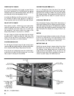
WIRING DIAGRAMS
ELEMENTARY DIAGRAM
LD02460
NOTES:
1. Field wiring to be in accordance with the current edition of the
National Electrical Code as well as all other applicable codes and
specifications.
2. Contacts must be suitable for switching 24VDC (gold contacts
recommended). Wiring shall not be run in the same conduit with
any line voltage wiring.
3. To cycle unit on and off automatically with contact shown, install
a cycling device in series with the flow switch (FLSW). See Note
2 for contact rating and wiring specifications.
4. To stop unit (Emergency Stop) with contacts other than those
shown, install the stop contact between terminals 5 and 1. If a
stop device is not installed, a jumper must be connected be-
tween terminals 5 and 1. Device must have a minimum contact
rating of 100VA at 115 volts A.C.
5. Contacts are rated at 115V, 100VA, resistive load only and must
be suppressed at load by user.
6. See installation, operation and maintenance manual.
7. Power factor correction capacitors may be installed on the chiller
electrical system (as shown) as a factory installed option.
8. Numbers along the right side of a diagram are line identification
numbers. The numbers at each line indicate the line number
location of relay contacts. An underlined contact location signi-
fies a normally closed contact. Numbers adjacent to circuit lines
are the circuit identification numbers.
LEGEND
Transient Voltage Suppression
Terminal Block for Customer Connections
Terminal Block for Customer Low Voltage
(Class 2) Connections. See Note 2
Terminal Block for YORK Connections Only
Wiring and Components by YORK
Optional Equipment
Wiring and/or Components by Others
T S
FIG. 6 – ELEMENTARY DIAGRAM
Summary of Contents for Millennium YCAJ150
Page 21: ...FORM 150 65 NM4 21 YORK INTERNATIONAL LD02461 FIG 6 ELEMENTARY DIAGRAM Cont d...
Page 22: ...22 YORK INTERNATIONAL ELEMENTARY DIAGRAM...
Page 24: ...24 YORK INTERNATIONAL CONNECTION DIAGRAM FIG 7 CONNECTION DIAGRAM LD02463...
Page 25: ...FORM 150 65 NM4 25 YORK INTERNATIONAL FIG 7 CONNECTION DIAGRAM Cont d LD02462...
Page 30: ...30 YORK INTERNATIONAL FIG 8 SYSTEM WIRING Cont d LD02499...
Page 100: ...100 YORK INTERNATIONAL LD02654 FIG 37B LOUVER BRACKETS INSTALLATION...
Page 103: ...FORM 150 65 NM4 103 YORK INTERNATIONAL LD02656 FIG 39A LOUVER INSTALLATION SIDES...
Page 104: ...104 YORK INTERNATIONAL LD02654 FIG 39B LOUVER BRACKETS INSTALLATION...
Page 108: ...108 YORK INTERNATIONAL FIG 40B CONDENSER COIL LOUVER INSTALLATION FRONT AND BACK LD02659...
Page 110: ...110 YORK INTERNATIONAL FIG 41 REMOTE RESET BOARD LD02666 P1...