


54
YORK INTERNATIONAL
The desired leaving water temperature is known as the
“Target” temperature which is the temperature the micro
will attempt to control to. The “Target” temperature is not
programmable, but it is always the midpoint of the Con-
trol Range (CR). Example: A control range of 44° - 46°F
(6.7 - 7.8°C) will have a “Target” Temp of 45°F (7.2°C),
which should equal the desired system leaving water
temperature. As mentioned before, the micro will be sat-
isfied with a leaving temperature between 44° - 45°F (6.7
- 7.2°C) unless the rate control is exceeded. The
microprocessor’s rate control is designed to be less re-
sponsive in the upper half of the Control Range (i.e. 45 -
46°F [7.2 - 7.8°C]) than in the lower half (i.e. 44° - 45°F
[6.7 - 7.2°C]). This is to prevent overshoot.
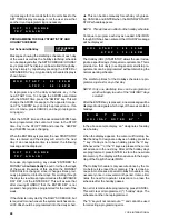
To program the Low-Limit Water Temperature (LWT) and
the Control Range (CR), press the CHILLED LIQUID
TEMP/RANGE key. This display will first exhibit a mes-
sage that “LEAVING WATER TEMP CONTROL” is se-
lected and 3 seconds later automatically scroll to the
next display of LWT and CR. The cursor will stop at the
first digit of LWT. Key in the Low-Limit Water Tempera-
ture (LWT) that is acceptable in the system. See below:
The micro will accept a range of programmable values
from 10.0 - 70.0°F (-12.2 - 21.1°C) (See “SWITCH 1”,
Page 37). If brine or glycol is used in the system, chilled
liquid temperatures below 40°F (4.4°C) may be desired.
To program setpoints below 40°F (4.4°C), Dip Switch 1,
Switch #1 on the Microprocessor Board must be prop-
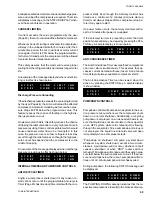
erly programmed. (See Page 37). If the switch is incor-
rect, when setpoints below 40°F (4.4°C) are entered as
well as when unacceptable values are entered, the fol-
lowing message will be displayed:
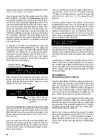
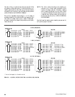
After the Low-Limit Water Temperature (LWT) is keyed
in, the lower limit of the CR (Control Range) in the dis-
play message will automatically change to a value iden-
tical to the “LWT”. See below:
min). Before RATE CONTROL can go into effect, the
water temperature would have to change at a very high
rate to exceed the RATE SENSITIVITY value pro-
grammed. This will assure normal loading will occur. 5°F/
min (2.8°C/min) also works well in comfort cooling appli-
cations. If unsure of a RATE SENSITIVITY selection,
use 5°F/min (2.8°C/min).
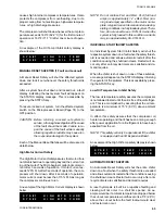
To program the RATE SENSITIVITY, first press the PRO-
GRAM key. Repetitively press the ENTER key until the
display below appears.
Key in the desired value and press the ENTER key. The
new value will be entered into memory and the display
will advance to the next user programmable limit.
The micro will accept a range of programmable values
between 0.5° - 5.0°F/min (0.3 - 2.8°C/min).
PROGRAMMING LEAVING WATER CONTROL
Chilled Liquid Temp/Range
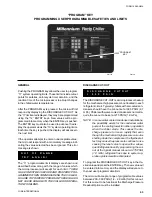
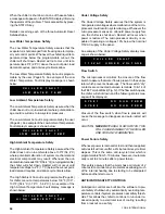
When the CHILLED LIQUID TEMP/RANGE key is
pressed, the following message will be displayed for 3
seconds indicating Dip Switch S1, Switch #4 on the Mi-
croprocessor Board is programmed properly:
If this message is incorrect, see the “SELECTION OF
RETURN OR LEAVING CHILLED LIQUID CONTROL”
Section (Page 50) for instructions to reprogram the Mi-
croprocessor Dip Switch S1, Switch #4.
The display will then scroll to a second message and hold:
This message will display the Low-Limit Water Tempera-
ture (LWT) and the Control Range (CR). In the sample
above, the LWT is 44.0°F (6.7°C) and the CR is 44° -
46°F (6.7 - 7.8°C).
The Control Range (CR) is the variation in leaving water
temperature which is acceptable in the system applica-
tion. As long as leaving water temperature stays between
the low limit and midpoint of the Control Range (CR), the
Microprocessor will consider the temperature acceptable
and will not initiate any loading/unloading reaction un-
less “Rate Control” requires. The Low-Limit Water Tem-
perature (LWT) is the minimum acceptable leaving water
temperature in the Control Range (CR), not the actual
user desired leaving water temperature setpoint.
R A T E
S E N S I T I V I T Y
=
5 . 0
F / M I N .
L E A V I N G
W A T E R
T E M P
C O N T R O L
L W T =
4 4 . 0
F
C R =
4 4 . 0
T O
4 6 . 0
F
O U T
O F
R A N G E
T R Y
A G A I N !
L W T =
4 4 . 0
F
C R =
4 4 . 0
T O
4 6 . 0
F
Low-Limit Water Temperature (LWT)
L W T =
4 4 . 0
F
C R =
4 4 . 0
T O
4 6 . 0
F
The lower limit of the CR will always auto-
matically equal LWT.
LWT
Summary of Contents for Millennium YCAJ150
Page 21: ...FORM 150 65 NM4 21 YORK INTERNATIONAL LD02461 FIG 6 ELEMENTARY DIAGRAM Cont d...
Page 22: ...22 YORK INTERNATIONAL ELEMENTARY DIAGRAM...
Page 24: ...24 YORK INTERNATIONAL CONNECTION DIAGRAM FIG 7 CONNECTION DIAGRAM LD02463...
Page 25: ...FORM 150 65 NM4 25 YORK INTERNATIONAL FIG 7 CONNECTION DIAGRAM Cont d LD02462...
Page 30: ...30 YORK INTERNATIONAL FIG 8 SYSTEM WIRING Cont d LD02499...
Page 100: ...100 YORK INTERNATIONAL LD02654 FIG 37B LOUVER BRACKETS INSTALLATION...
Page 103: ...FORM 150 65 NM4 103 YORK INTERNATIONAL LD02656 FIG 39A LOUVER INSTALLATION SIDES...
Page 104: ...104 YORK INTERNATIONAL LD02654 FIG 39B LOUVER BRACKETS INSTALLATION...
Page 108: ...108 YORK INTERNATIONAL FIG 40B CONDENSER COIL LOUVER INSTALLATION FRONT AND BACK LD02659...
Page 110: ...110 YORK INTERNATIONAL FIG 41 REMOTE RESET BOARD LD02666 P1...