


72
YORK INTERNATIONAL
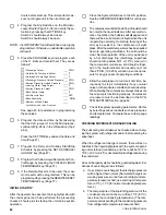
This display informs the operator whether SYS 1 liquid
line solenoid was energized (ON) or de-energized (OFF)
at the time of the fault.
This message informs the operator if SYS 1 Run Per-
missive (flow switch, remote START/STOP) was in the
RUN mode (ON) or (STOP) mode (OFF).
This message indicates the number of stages which were
loaded on SYS 1 at the time of the fault.
This display indicates the number of fans on SYS 1 which
were running forward at the time of the fault.
This message indicates the number of fans on SYS 1
which were running in the reverse direction at the time of
the fault.
This display indicates whether the Hot Gas Solenoid
Valve was energized on SYS 1 at the time of the fault.
NOTE: The micro will attempt to control the Hot Gas
Solenoid Valve regardless of whether the option
is installed.
This message indicates whether Compressor 2 was ON
or OFF at the time of the fault.
This message indicates SYS 2 motor current at the time
of the fault.
This message indicates the type of chilled water control
selected at the time of the fault. LCHWT = Leaving Wa-
ter Control. ECHWT = Entering or Return Water Control.
This display shows the Cooling Range (CONTROL
RANGE, CR) which was selected at the time of the fault.
This message indicated the entering condenser water
temperature at the time of the fault. A fixed value will be
displayed if the optional sensor is not installed.
This message indicates the leaving condenser water tem-
perature at the time of the fault. A fixed value will be
displayed if the optional sensor is not installed.
This message indicates whether Compressor 1 was ON
or OFF at the time of the fault.
This message indicates SYS 1 motor current at the time
of the fault.
This display shows the suction pressure of SYS 1 at the
time of the fault.
This message indicates SYS 1 discharge pressure at
the time of the fault. This display will be a fixed value
unless the Discharge Pressure Readout is installed.
This display shows the oil pressure of SYS 1 at the time
of the fault.
S Y S
1
F O R W A R D
F A N S
2
S Y S
1
R E V E R S E
F A N S
O F F
S Y S
1
H O T
G A S
V A L V E
O F F
S Y S
2
C O M P R E S S O R
O F F
S Y S
2
M O T O R
A M P S
6 0 % F L A
S Y S
1
C O M P R E S S O R
O N
S Y S
1
M O T O R
A M P S
7 4 % F L A
S Y S
1
S U C T I O N
P R E S S
5 9
P S I G
S Y S
1
D S C H
P R E S S
2 2 0
P S I G
C O N T R O L
T Y P E
L C H W T
S Y S
1
O I L
P R E S S U R E
7 0
P S I D
C O O L I N G
R A N G E
4 5 . 0
T O
4 7 . 0
D E G F
S Y S
1
L I Q
L I N E
O N
E N T E R I N G
C O N D
W A T E R
8 0 . 1
S Y S
1
R U N
P E R M I S S I V E
O N
L E A V I N G
C O N D
W A T E R
9 0 . 5
S Y S
1
L O A D I N G
S T A G E S
1
Summary of Contents for Millennium YCAJ150
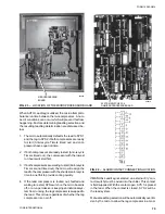
Page 21: ...FORM 150 65 NM4 21 YORK INTERNATIONAL LD02461 FIG 6 ELEMENTARY DIAGRAM Cont d...
Page 22: ...22 YORK INTERNATIONAL ELEMENTARY DIAGRAM...
Page 24: ...24 YORK INTERNATIONAL CONNECTION DIAGRAM FIG 7 CONNECTION DIAGRAM LD02463...
Page 25: ...FORM 150 65 NM4 25 YORK INTERNATIONAL FIG 7 CONNECTION DIAGRAM Cont d LD02462...
Page 30: ...30 YORK INTERNATIONAL FIG 8 SYSTEM WIRING Cont d LD02499...
Page 100: ...100 YORK INTERNATIONAL LD02654 FIG 37B LOUVER BRACKETS INSTALLATION...
Page 103: ...FORM 150 65 NM4 103 YORK INTERNATIONAL LD02656 FIG 39A LOUVER INSTALLATION SIDES...
Page 104: ...104 YORK INTERNATIONAL LD02654 FIG 39B LOUVER BRACKETS INSTALLATION...
Page 108: ...108 YORK INTERNATIONAL FIG 40B CONDENSER COIL LOUVER INSTALLATION FRONT AND BACK LD02659...
Page 110: ...110 YORK INTERNATIONAL FIG 41 REMOTE RESET BOARD LD02666 P1...