


FORM 150.65-NM4
73
YORK INTERNATIONAL
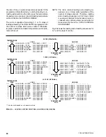
This message indicates the number of stages which were
loaded on SYS 2 at the time of the fault.
This display indicates the number of fans on SYS 2 which
were running forward at the time of the fault.*
This message indicates the number of fans on SYS 2
which were running in the reverse direction at the time of
the fault.
This display indicates whether the Hot Gas Solenoid
Valve was energized on SYS 2 at the time of the fault.
NOTE: The micro will attempt to control the Hot Gas
Solenoid Valve regardless of whether the option
is installed.
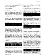
S Y S
2
O I L
P R E S S U R E
7 4
P S I D
S Y S
2
L I Q
L I N E
O N
S Y S
2
R U N
P E R M I S S I V E
O N
S Y S
2
L O A D I N G
S T A G E S
1
S Y S
2
F O R W A R D
F A N S
O F F
S Y S
2
S U C T I O N
P R E S S
6 2
P S I G
S Y S
2
R E V E R S E
F A N S
O F F
S Y S
1
D S C H
P R E S S
2 4 0
P S I G
S Y S
1
H O T
G A S
V A L V E
O F F
This display shows the suction pressure of SYS 2 at the
time of the fault.
This message indicates SYS 2 discharge pressure at
the time of the fault. This display will be a fixed value
unless the Discharge Pressure Readout is installed.
This display shows the oil pressure of SYS 2 at the time
of the fault.
This display informs the operator whether SYS 2 liquid
line solenoid was energized (ON) or de-energized (OFF)
at the time of the fault.
This message informs the operator if SYS 2 Run Per-
missive (flow switch, remote START/STOP) was in the
RUN mode (ON) or STOP mode (OFF).
Summary of Contents for Millennium YCAJ150
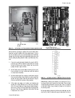
Page 21: ...FORM 150 65 NM4 21 YORK INTERNATIONAL LD02461 FIG 6 ELEMENTARY DIAGRAM Cont d...
Page 22: ...22 YORK INTERNATIONAL ELEMENTARY DIAGRAM...
Page 24: ...24 YORK INTERNATIONAL CONNECTION DIAGRAM FIG 7 CONNECTION DIAGRAM LD02463...
Page 25: ...FORM 150 65 NM4 25 YORK INTERNATIONAL FIG 7 CONNECTION DIAGRAM Cont d LD02462...
Page 30: ...30 YORK INTERNATIONAL FIG 8 SYSTEM WIRING Cont d LD02499...
Page 100: ...100 YORK INTERNATIONAL LD02654 FIG 37B LOUVER BRACKETS INSTALLATION...
Page 103: ...FORM 150 65 NM4 103 YORK INTERNATIONAL LD02656 FIG 39A LOUVER INSTALLATION SIDES...
Page 104: ...104 YORK INTERNATIONAL LD02654 FIG 39B LOUVER BRACKETS INSTALLATION...
Page 108: ...108 YORK INTERNATIONAL FIG 40B CONDENSER COIL LOUVER INSTALLATION FRONT AND BACK LD02659...
Page 110: ...110 YORK INTERNATIONAL FIG 41 REMOTE RESET BOARD LD02666 P1...