


8 Adjustments
8.5.1 Explanation of Servo Gain
8-20
8.5 Manual Tuning
8.5.1 Explanation of Servo Gain
To adjust the servo gain manually, understand the configuration and characteristics of the SERVOPACK and
adjust the servo gain parameters one by one. If one parameter is changed, it is almost always necessary to adjust
the other parameters. It will also be necessary to make preparations such as setting up a measuring instrument to
monitor the output waveform from the SERVOPACK.
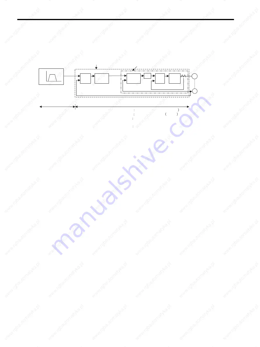
The SERVOPACK has three feedback loops (i.e., position loop, speed loop, and current loop). The innermost
loop must have the highest response and the middle loop must have higher response than the outermost. If this
principle is not followed, it will result in vibration or responsiveness decreases.
The SERVOPACK is designed to ensure that the current loop has good response performance. The user need to
adjust only position loop gain and speed loop gain.
8.5.2 Servo Gain Manual Tuning
The SERVOPACK has the following parameters for the servo gains. Setting the servo gains in the parameters
can adjust the servo responsiveness.
• Pn100: Speed loop gain (Kv)
• Pn101: Speed loop integral time constant (Ti)
• Pn102: Position loop gain (Kp)
• Pn401: 1st Step 1st torque reference filter time constant (Tf)
For the position and speed control, the adjustment in the following procedure can increase the responsiveness.
The positioning time in position control can be reduced.
Perform the manual tuning in the following cases.
• If the advanced autotuning and one-parameter tuning did not give a satisfactory result.
• To increase the servo gains more than the values set by the advanced autotuning and the one-parameter
autotuning.
• To determine the servo gains and moment of inertia ratio by the user.
Start the manual tuning from the factory setting or the values set by the advanced autotuning and the one-
parameter autotuning. Prepare measuring instruments such as memory recorder so that the signals can be
observed from the analog monitor (CN5) such as “Torque Reference” and “Motor Speed,” and “Position Error
Monitor” for the position control. (Refer to
8.7 Analog Monitor
.)
Vibration may occur during servo gain adjustments. Validate the vibration alarm, Pn310=n.
2 to detect
vibration. Vibration alarm can not detect all vibration. When vibration alarm occurred, an emergency stop device
is needed to stop the machine. Customers have to provide the emergency stop device, and use this device when
vibration occurred.
Encoder
Position control loop
Speed control loop
Speed
Speed pattern
Time
Move
reference
Error
counter
Position
loop
gain
Kp
Speed
control
section
Kv
Ti
+
-
Current
control
section
Electric
power
converting
Servomotor
M
PG
Position loop
SERVOPACK
Host controller
(provided by user)
Kp Position Loop Gain (Pn102
Kv Speed Loop Gain Pn100
Ti
Speed Loop Integral Time
Constant (Pn101)
Tf 1st Step 1st Torque Reference Filter Time
Constant (Pn401)
+
-
+
-
Speed
reference
Speed loop
Current loop
Tf
Summary of Contents for SGDS Sigma III Series
Page 3: ...SGDS Sigma III Servo Amplifier User Manual for Mechatrolink II Communications...
Page 21: ......
Page 59: ...2 System Selection 2 5 4 Regenerative Resistors 2 28...
Page 68: ...3 3 SERVOPACK Internal Block Diagrams 3 9 3 3 3 Three phase 200 V 1 0 kW...
Page 82: ...3 7 Dimensional Drawings of Base mounted SERVOPACK Model SGDS 12A 12A 3 23 Three phase 1 5kW...
Page 133: ...5 Wiring 5 7 2 Connecting Externally Regenerative Resistors 5 28...
Page 229: ...7 Operation 7 7 4 Absolute Encoder Home Position Offset 7 38...


