


11 Appendix
11.2.2 List of Parameters
11-18
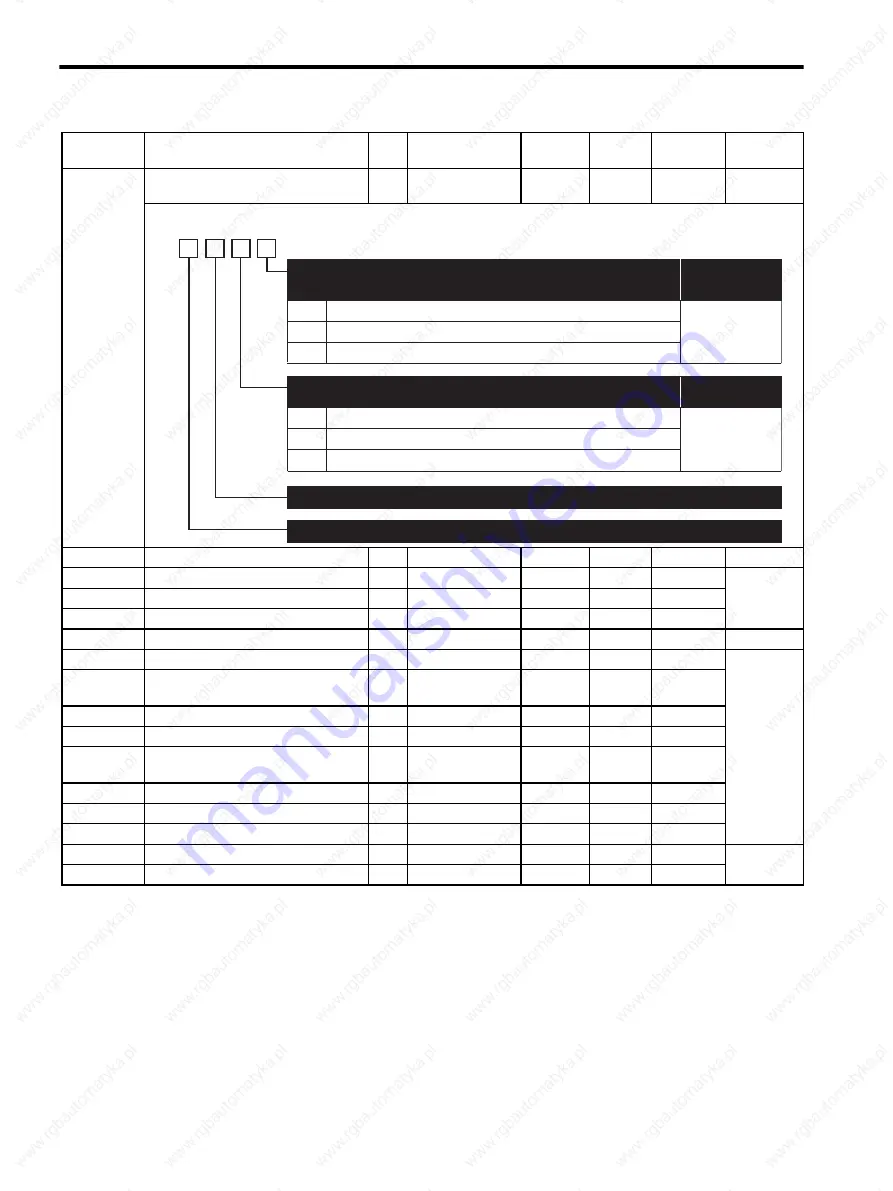
Pn110
Normal Autotuning Switches
2
−
−
0012
∆
/
8.2.3
8.6.5
Pn111
Speed Feedback Compensation Gain *
2
1 to 500%
1%
100%
8.6.5
Pn119
Reference Filter Gain
2
1 to 2000.0/s
0.1/s
50.0/s
8.6.8
Pn11A
Reference Filter Gain Compensation
2
50.0 to 200.00 %
0.1 %
100.0 %
Pn11E
Reference Filter Bias (Forward)
2
0.0 to 1000.0 %
0.1 %
100.0 %
Pn11F
Position Integral Time Constant
2
0.0 to 5000.0 ms
0.1 ms
0.0 ms
8.6.12
Pn12B
3rd Speed Loop Gain
2
1.0 to 2000.0 Hz
0.1 Hz
40.0 Hz
8.6.6
Pn12C
3rd Speed Loop Integral Time
Constant
2
0.15 to 512.00 ms
0.01 ms
20.00 ms
Pn12D
3rd Position Loop Gain
2
1.0 to 2000.0 /s
0.1 /s
40.0 /s
Pn12E
4th Speed Loop Gain
2
1.0 to 2000.0 Hz
0.1 Hz
40.0 Hz
Pn12F
4th Speed Loop Integral Time
Constant
2
0.15 to 512.00 ms
0.01 ms
20.00 ms
Pn130
4th Position Loop Gain
2
1.0 to 2000.0 /s
0.1 /s
40.0 /s
Pn131
Gain Switching Time1
2
0 to 65535 ms
1 ms
0 ms
Pn132
Gain Switching Time 2
2
0 to 65535 ms
1 ms
0 ms
Pn135
Gain Switching Waiting Time 1
2
0 to 65535 ms
1 ms
0 ms
8.6.6
Pn136
Gain Switching Waiting Time 2
2
0 to 65535 ms
1 ms
0 ms
* The parameter Pn111 setting is enabled only when the parameter Pn110.1 is set to “0.”
Note:
: Can be changed at any time, and immediately validated after changing. (Called an online
parameter.)
∆
: Validated after a Set Up Device command is sent, when loading and using parameters at
power ON. Also validated when turning OFF and then ON the power supply again after a
Write Non-volatile Parameter (PPRM_WR) command is sent.
Parameter
No.
Name
Data
Size
Setting Range
Units
Factory
Setting
Changing
Method
Reference
Section
0
1
2
0
1
Performs normal autotuning
only when operation starts.
Always
performs normal autotuning.
Performs
manual tuning
but not normal autotuning.
Available.
N/A
Reserved (Do not change)
Normal Autotuning Method
(Refer to "11.3.1 Autotuning,
8.2.3 Selecting the Normal Autotuning Execution Method.")
Changing Method
Changing Method
Speed Feedback Compensation Selection
(Refer to "8.6.5 Speed Feedback Compensation.")
Reserved (Do not change)
4th
digit
3rd
digit
2nd
digit
1st
digit
n.
Reserved (Do not change)
2 to 3
∆
Summary of Contents for SGDS Sigma III Series
Page 3: ...SGDS Sigma III Servo Amplifier User Manual for Mechatrolink II Communications...
Page 21: ......
Page 59: ...2 System Selection 2 5 4 Regenerative Resistors 2 28...
Page 68: ...3 3 SERVOPACK Internal Block Diagrams 3 9 3 3 3 Three phase 200 V 1 0 kW...
Page 82: ...3 7 Dimensional Drawings of Base mounted SERVOPACK Model SGDS 12A 12A 3 23 Three phase 1 5kW...
Page 133: ...5 Wiring 5 7 2 Connecting Externally Regenerative Resistors 5 28...
Page 229: ...7 Operation 7 7 4 Absolute Encoder Home Position Offset 7 38...


