


8 Adjustments
8.6.10 Vibration Suppression on Stopping
8-48
1. Sufficient precautions must be taken when setting the notch frequencies. Do not set the notch frequencies
(Pn409 or Pn40C) that is close to the speed loop’s response frequency. Set the frequencies at least four
times higher than the speed loop’s response frequency. Setting the notch frequency too close to the
response frequency may cause vibration and damage the machine. The speed loop response frequency is
the value of the Speed Loop Gain (Pn100) when the Moment of Inertia Ratio (Pn103) is set to the correct
value.
2. Change the Notch Filter Frequency (Pn409 or Pn40B) only when the motor is stopped. Vibration may
occur if the notch filter frequency is changed when the motor is rotating.
8.6.10 Vibration Suppression on Stopping
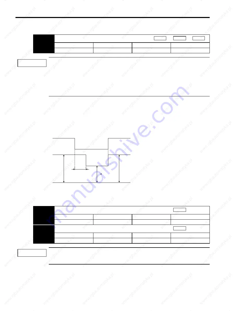
When the servo gain has been increased, there may be vibration upon stopping (e.g., limit cycle) even though
there is no vibration during operation. The function to suppress vibration on stopping, lowers the internal servo
gain only when stopping. After the time specified fo
r the
Vibration Suppression Starting Time (Pn421
)
has elapsed
from the time the difference of position reference becomes zero the internal servo gain is reduced at the rate
specified for the
Damping for Vibration Suppression on Stopping
(Pn420)
.
Set the
Damping for Vibration Suppression on stopping (Pn420)
is 50
%
or higher, and the
Vibration
Suppression Starting Time (Pn421)
to 10 ms or longer. If lower value are set, the response characteristic
may become worse and vibration may occur.
Pn40D
2nd Step Notch Filter Q Value
Setting Range
Setting Unit
Factory Setting
Setting Validation
0.50 to 10.00
0.01
0.70
Immediately
Speed
Position
Torque
IMPORTANT
Difference of
Position reference
Servo gain
Difference of
Position reference = 0
K Pn420/100
K
K
Pn421
Pn420
Damping for Vibration Suppression on Stopping
Setting Range
Setting Unit
Factory Setting
Setting Validation
10% to 100%
1%
100%
Immediately
Pn421
Vibration Suppression Starting Time
Setting Range
Setting Unit
Factory Setting
Setting Validation
0 to 65,535 ms
1 ms
1,000 ms
Immediately
Position
Position
IMPORTANT
Summary of Contents for SGDS Sigma III Series
Page 3: ...SGDS Sigma III Servo Amplifier User Manual for Mechatrolink II Communications...
Page 21: ......
Page 59: ...2 System Selection 2 5 4 Regenerative Resistors 2 28...
Page 68: ...3 3 SERVOPACK Internal Block Diagrams 3 9 3 3 3 Three phase 200 V 1 0 kW...
Page 82: ...3 7 Dimensional Drawings of Base mounted SERVOPACK Model SGDS 12A 12A 3 23 Three phase 1 5kW...
Page 133: ...5 Wiring 5 7 2 Connecting Externally Regenerative Resistors 5 28...
Page 229: ...7 Operation 7 7 4 Absolute Encoder Home Position Offset 7 38...


