


7.7 Absolute Encoders
7-35
7.7.3 Multi-turn Limit Setting
When implementing absolute detection systems for machines that turn m times in response to n turns in the load
shaft, such as circular tables, it is convenient to reset the multi-turn data from the encoder to 0 every m turns. The
Multi-turn Limit
1
Setting allows the value m to be set for the encoder.
Select the absolute encoder usage with the following parameter.
“0” in Pn002.2 must be set in order to enable the absolute encoder.
The multi-turn limit is set in the SERVOPACK using the following parameter.
If the Multi-turn Limit Setting is set to 65535 (factory setting), the multi-turn data will vary from -32768 to
32767. If any other value is set, the multi-turn data will vary from 0 to the setting of Pn205.
If the servomotor rotates in the negative direction from 0, the multi-turn data will change to the value set in
Pn205. If the servomotor rotates in the positive direction from the value set in Pn205, the multi-turn data will
change to 0. Set Pn205 to m - 1.
The setting is enabled by turning OFF the control power and turning it ON again.
• Changing the multi-turn limit may change the absolute position data. Be sure to set the multi-turn
limit following the controller’s designation.
• If the Multi-turn Limit Disagreement (A. CCO) alarm occurs, check the setting of parameter Pn205
in the SERVOPACK to be sure that it is correct.
If Fn013 is executed when an incorrect value is set in Pn205, an incorrect value will be set in the encoder.
The alarm will disappear even if an incorrect value is set, but incorrect positions will be detected. The
machine will move to an unexpected positions, resulting in damages to the machine or in a fatal accident..
WARNING
1
Multi-turn limit
The upper limit of multi-turn data. The multi-turn data will vary between 0 and the value of Pn205 (multi-turn limit set-
ting) .
TERMS
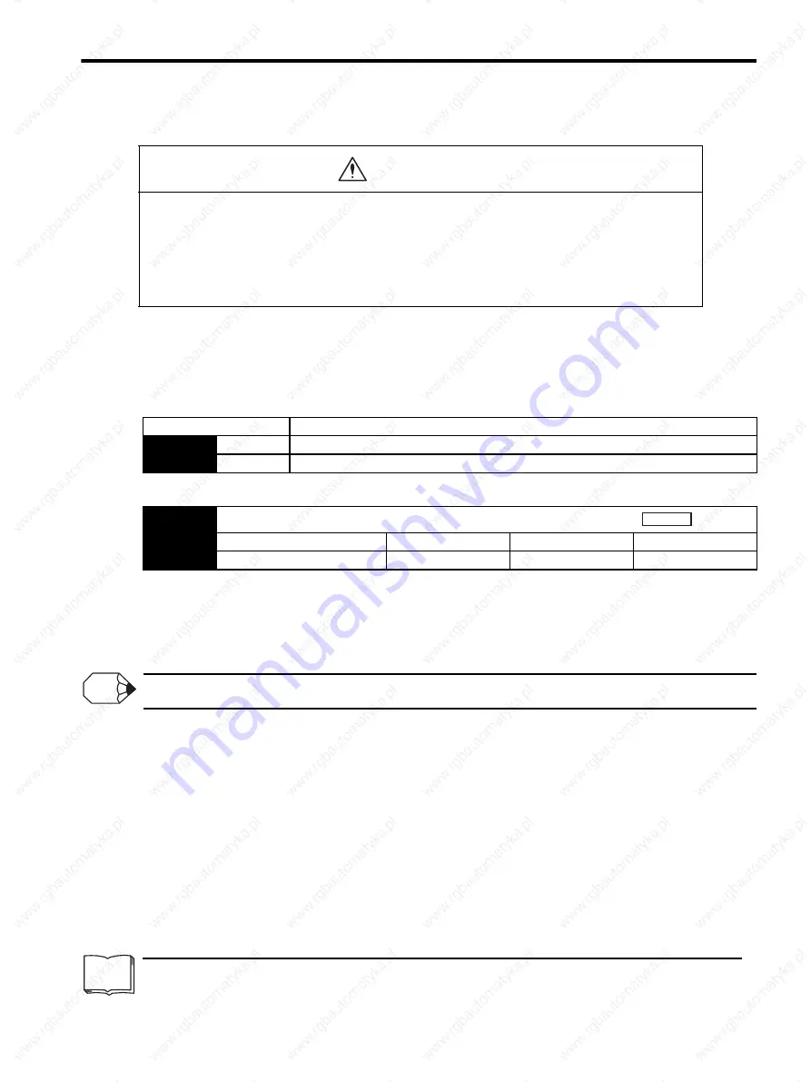
Parameter
Description
Pn002
n.
0
Use the absolute encoder as an absolute encoder.
n.
1
Use the absolute encoder as an incremental encoder.
Pn205
Multi-turn Limit Setting
Setting Range
Setting Unit
Factory Setting
Setting Validation
0 to 65535
1 rev
65535
After restart
Position
INFO
Summary of Contents for SGDS Sigma III Series
Page 3: ...SGDS Sigma III Servo Amplifier User Manual for Mechatrolink II Communications...
Page 21: ......
Page 59: ...2 System Selection 2 5 4 Regenerative Resistors 2 28...
Page 68: ...3 3 SERVOPACK Internal Block Diagrams 3 9 3 3 3 Three phase 200 V 1 0 kW...
Page 82: ...3 7 Dimensional Drawings of Base mounted SERVOPACK Model SGDS 12A 12A 3 23 Three phase 1 5kW...
Page 133: ...5 Wiring 5 7 2 Connecting Externally Regenerative Resistors 5 28...
Page 229: ...7 Operation 7 7 4 Absolute Encoder Home Position Offset 7 38...


