Manual 85580V2
5009 Installation/Hardware
Woodward
69
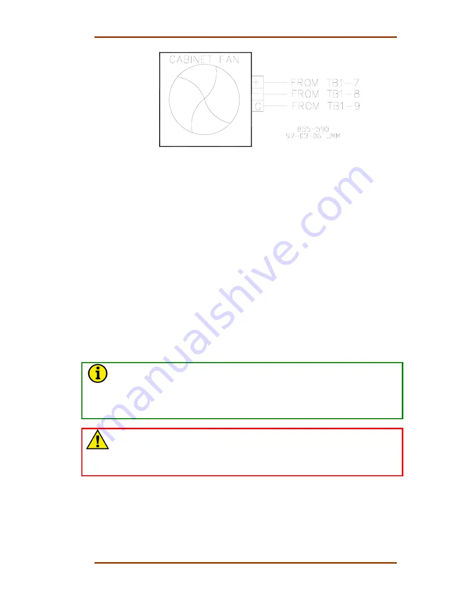
Figure 4-30. Cabinet Fan Diagram
System Power-Up
If at any time during this procedure the defined or expected result is not
achieved, step to Chapter 5 of this volume and begin system troubleshooting.
1. Turn the power for one power supply on and verify that the power supply’s
green LED is the only power supply LED on.
2. Turn the power for second power supply on and verify that the power
supply’s green LED is the only power supply LED on.
3. Momentarily toggle the A, B, and C-Rack’s CPU RESET switch up (press the
switch’s top half), then back to its normal down position (press the switch’s
bottom half).
At this point the system will perform off-line diagnostics, this diagnostics testing
could take a couple of minutes. When all CPUs have synchronized and
completed their diagnostic tests, no red LEDs should be on, and the control will
begin running the application program.
NOTE
When the RESET switch is toggled to the down position the CPU’s red Fault
and Watchdog LEDs should go out and the green RUN LED should go on. At
this time the CPU is performing the self-diagnostics and boot-up processes.
If only one CPU has been reset (other CPUs still failed) the 5009 will wait for
another CPU to boot-up before both CPUs will go to a running state.
WARNING—VERIFY CALIBRATION
Improperly calibrated devices can cause turbine damage and possible
personnel injury or death. Before starting the turbine for the first time, and
periodically thereafter, verify the calibration of all external input and output
devices.
Summary of Contents for MicroNet TMR 5009
Page 8: ...5009 Installation Hardware Manual 85580V2 vi Woodward...
Page 23: ...Manual 85580V2 5009 Installation Hardware Woodward 15 Figure 3 1 Hardware Identification...
Page 33: ...Manual 85580V2 5009 Installation Hardware Woodward 25 Figure 3 7 DIN Rail ATM Outline Drawing...
Page 35: ...Manual 85580V2 5009 Installation Hardware Woodward 27 Figure 3 9 DTM Outline Drawing...
Page 36: ...5009 Installation Hardware Manual 85580V2 28 Woodward Figure 3 10 DTM Mounting Configuration...
Page 68: ...5009 Installation Hardware Manual 85580V2 60 Woodward Figure 4 19 System Cable Layout Diagram...
Page 69: ...Manual 85580V2 5009 Installation Hardware Woodward 61 Figure 4 20 Power Supply Wiring Diagram...
Page 70: ...5009 Installation Hardware Manual 85580V2 62 Woodward Figure 4 21 ATM 1 Wiring Diagram...
Page 71: ...Manual 85580V2 5009 Installation Hardware Woodward 63 Figure 4 22 ATM 2 Wiring Diagram...
Page 72: ...5009 Installation Hardware Manual 85580V2 64 Woodward Figure 4 23 DTM 1 Wiring Diagram...
Page 73: ...Manual 85580V2 5009 Installation Hardware Woodward 65 Figure 4 24 DTM 2 Wiring Diagram...
Page 74: ...5009 Installation Hardware Manual 85580V2 66 Woodward Figure 4 25 DTM 3 Wiring Diagram...
Page 75: ...Manual 85580V2 5009 Installation Hardware Woodward 67 Figure 4 26 DTM 4 Wiring Diagram...
Page 89: ...Manual 85580V2 5009 Installation Hardware Woodward 81 Table 5 3 Discrete In Cable Connections...
Page 90: ...5009 Installation Hardware Manual 85580V2 82 Woodward Table 5 4 Relay Cable Connections...
Page 91: ...Manual 85580V2 5009 Installation Hardware Woodward 83 Table 5 4 Relay Cable Connections cont...
Page 92: ...5009 Installation Hardware Manual 85580V2 84 Woodward Table 5 5 Analog Combo Module...
Page 103: ...Manual 85580V2 5009 Installation Hardware Woodward 95 Figure 8 2 Operator Control Panel...
Page 108: ...5009 Installation Hardware Manual 85580V2 100 Woodward Figure 8 6 Real Power Sensor...
Page 115: ......
Page 116: ...Declarations...
Page 117: ......


