background image

5009 Installation/Hardware 

Manual 85580V2 


Woodward 

MPU and Analog I/O Module (A3) 

 
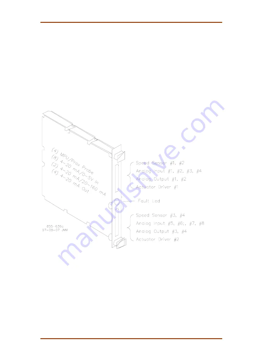
Each analog module contains circuitry for four speed sensor inputs, eight analog 
inputs, four analog outputs, and two proportional actuator outputs. An on-board 
micro-controller scales inputs and outputs using calibration constants stored in 
EEPROM, and schedules outputs to occur at the proper time. Refer to Figure  
2-5. This module includes no potentiometers and requires no calibration. When a 
channel or module fault is detected, the control annunciates the fault, disables 
the channel or module and does not use the channel/module’s data in system 
calculations or control. 
 
Each CPU sends and receives information to and from its respective MPU & 
Analog I/O module via the VME bus. Each input value is stored in a register and 
addressed by the CPU as required. Outputs are driven by the CPU, through the 
module’s associated output drivers. 


Figure 2-5. MPU and Analog I/O Module 


Analog Termination Modules 

 
Analog Termination Modules (ATMs) mount external to the 5009 chassis on a 
standard DIN rail. The analog termination modules are used to connect analog 
field wiring to the 5009 control. An ATM houses circuitry to: 

• 

route each input signal to the system’s three independent (rack mounted) 
analog modules 

• 

produce each output signal by summing the three independent analog 
modules’ respective outputs 

Summary of Contents for MicroNet TMR 5009

Page 1: ...MicroNet TMR 5009 Digital Control System Volume 2 Installation Hardware Manual Manual 85580V2 Revision E...

Page 2: ...orized modifications i constitute misuse and or negligence within the meaning of the product warranty thereby excluding warranty coverage for any resulting damage and ii invalidate product certificati...

Page 3: ...n Modules 26 Install OpView Interface if included 29 CHAPTER 4 ELECTRICAL INSTALLATION 31 Introduction 31 Cabinet if included 31 System Cables if cabinet is not included 31 Shields and Grounding 32 In...

Page 4: ...Termination Module Diagram 9 Figure 2 7 Discrete Input Output Module 10 Figure 2 8 DTM Block Diagram 12 Figure 2 9 SIO Module Block Diagram 13 Figure 3 1 Hardware Identification 15 Figure 3 2 Cabinet...

Page 5: ...gram 59 Figure 4 19 System Cable Layout Diagram 60 Figure 4 20 Power Supply Wiring Diagram 61 Figure 4 21 ATM 1 Wiring Diagram 62 Figure 4 22 ATM 2 Wiring Diagram 63 Figure 4 23 DTM 1 Wiring Diagram 6...

Page 6: ...ion 2 hazardous locations if an F T Relay module is installed in the cabinet It is to be used in Ordinary or non hazardous locations only Substitution of components may impair suitability for Class I...

Page 7: ...plastic or Styrofoam cups cup holders cigarette packages cellophane wrappers vinyl books or folders plastic bottles and plastic ash trays away from the control the modules and the work area as much a...

Page 8: ...5009 Installation Hardware Manual 85580V2 vi Woodward...

Page 9: ...DDE tag names Modbus is a registered trademark of Modicon Inc Volume 4 provides details on installation and operation of the OpView operator control station if provided with your system Active 5009 pa...

Page 10: ...guration the failure of any one section will not cause a shutdown Each kernel section includes a kernel power supply a CPU an analog I O module and a discrete I O module Slot to slot logic and power c...

Page 11: ...es of power supplies main power supplies and kernel power supplies The control s power chassis contains two plug in main power supplies which provide 24 V to each kernel section A B C of the 5009 cont...

Page 12: ...are made through panel mounted Phoenix type terminal blocks See Figure 4 20 A standard 50 pin ribbon cable is used for connecting the power supply chassis to the 5009 control chassis A set of two main...

Page 13: ...and verified by its respective kernel CPU Figure 2 2 Kernel Power Supply Block Diagram Central Processor Unit CPU Module A2 This module following the instructions of the application program controls t...

Page 14: ...arge the Real Time Clock will need to be set once the CPU is powered up The module will automatically recharge the battery once powered See the battery specifications in Chapter 6 Figure 2 3 CPU Modul...

Page 15: ...Manual 85580V2 5009 Installation Hardware Woodward 7 Figure 2 4 CPU Communications Port Filter Kit Installation Instructions...

Page 16: ...not use the channel module s data in system calculations or control Each CPU sends and receives information to and from its respective MPU Analog I O module via the VME bus Each input value is stored...

Page 17: ...ype of probe used Depending on a MPU s limitations each MPU input can be jumper configured to allow it to drive either two or three inputs some MPUs cannot drive three inputs See Chapter 6 of this man...

Page 18: ...ze relays Output Relays are located on the Discrete Termination Modules Each output channel has a readback buffer that stores and indicates the status of the output driver and associated relays The CP...

Page 19: ...ed See Figure 4 9 CAUTION MAXIMUM VOLTAGE To comply with CE Marking under the European Low Voltage Directive LVD the maximum external circuit voltage for both the Discrete Inputs and Relay Output circ...

Page 20: ...apable of utilizing two SIO modules at any time These modules are installed in slot 5 of the A and B kernels Each SIO module includes four serial ports Ports 1 and 2 are RS 232 communications based po...

Page 21: ...cabinet diagrams This panel is a UL Listed industrial control panel OpView Operator Interface optional The OpView Operator Interface is a computer based work station that functions as a touch screen...

Page 22: ...packing carton s and checked to make sure you have all the necessary components before attempting to assemble and install the system Refer to Table 3 1 and Figure 3 1 Table 3 1 System Components Desi...

Page 23: ...Manual 85580V2 5009 Installation Hardware Woodward 15 Figure 3 1 Hardware Identification...

Page 24: ...odule is suitable for use in non hazardous locations only Use the following procedures to install a system in the selected location Installation procedures are included to for systems provided with an...

Page 25: ...Manual 85580V2 5009 Installation Hardware Woodward 17 Figure 3 2 Cabinet Dimensions Before beginning installation successfully identify all components and read this entire chapter...

Page 26: ...Drill and tap mounting holes using a 21 0 156 0 164 drill bit and a 10 32 tap 3 Connect the W1 B cable between both the control and power chassis Refer to Figure 3 3 Quick connect terminals allow for...

Page 27: ...er to Figures 3 4 3 5 and 3 6 3 Align the circuit board edges in the card guides and push the module into the slot until the connector on the module and the connector on the motherboard make contact 4...

Page 28: ...5009 Installation Hardware Manual 85580V2 20 Woodward Figure 3 4a Outline Drawing of 5009 Main Chassis...

Page 29: ...Manual 85580V2 5009 Installation Hardware Woodward 21 Figure 3 4b Outline Drawing of 5009 Main Chassis...

Page 30: ...5009 Installation Hardware Manual 85580V2 22 Woodward Figure 3 4c Outline Drawing of 5009 Power Chassis...

Page 31: ...Manual 85580V2 5009 Installation Hardware Woodward 23 Figure 3 5 Outline Diagram of Module with Label Figure 3 6 Module Location Diagram...

Page 32: ...cm and install DIN rail using the appropriate screws and washers 3 Verify that the DIN rail is at earth ground potential connected to a panel that is at earth ground potential If the DIN rail is not a...

Page 33: ...Manual 85580V2 5009 Installation Hardware Woodward 25 Figure 3 7 DIN Rail ATM Outline Drawing...

Page 34: ...ave sufficient space between the DTM and walls objects etc for easy access The master DTMs 1 3 must be mounted directly above the slave DTMs 2 4 within a maximum distance 2 Drill and tap mounting hole...

Page 35: ...Manual 85580V2 5009 Installation Hardware Woodward 27 Figure 3 9 DTM Outline Drawing...

Page 36: ...5009 Installation Hardware Manual 85580V2 28 Woodward Figure 3 10 DTM Mounting Configuration...

Page 37: ...stem optionally a longer cable up to 15 m 50 ft can be used Option 1 1 Mark OpView mounting hole locations taking care to leave sufficient space between the OpView and walls objects etc for easy acces...

Page 38: ...09 Installation Hardware Manual 85580V2 30 Woodward Option 2 Place the OpView in position install the six mounting clamps to secure the unit into place and tighten securely Figure 3 12 Mounting Templa...

Page 39: ...ons step to the system cables instruction then step to the next set of instructions etc The PCI software wiring list must be created to assist in electrical installation see Volume 3 The wiring list w...

Page 40: ...rmly pressing each connector into its receptacle until the fasteners are closed Refer to Table 3 1 for cable identification and Figure 4 19 for cable connection diagram After cable installation replac...

Page 41: ...and current For AC sources this power rating is stated in Volt Amps VA The maximum VA of a source can be calculated by taking the rated output voltage times the maximum output current at that voltage...

Page 42: ...e maximum inrush current Time delay fuses or circuit breakers must be used to avoid nuisance trips The 5009 control includes a set of two main power supplies Input power ratings are identified in Tabl...

Page 43: ...rotor coupling An application may use any combination of the accepted speed probes All speed sensing inputs use the same programmed gear ratio and number of teeth to calculate speed thus the speed pr...

Page 44: ...e of probe used Short circuit protected 12 Vdc and 24 Vdc sources with isolation diodes on the power common and output source lines are provided with each speed input to power system proximity probes...

Page 45: ...Manual 85580V2 5009 Installation Hardware Woodward 37 Figure 4 3a Example 24 V Proximity Probe Wiring Diagram Figure 4 3b Example 12 V Proximity Wiring Diagram...

Page 46: ...24 V output the 12 V is current limited to 100 mA and located on the ATMs Proximity Probes only External pull up resistors are required when interfacing with an open collector type of proximity probe...

Page 47: ...l of reaching over 200 Vdc with respect to the control s common the use of a loop isolator is recommended to break any return current paths which could result in erroneous readings All eight analog in...

Page 48: ...less and have its outputs fused with appropriate sized fuses a maximum current rating of 100 V where V is the supply s rated voltage or 5 A whichever is less It is recommended that 0 75 mm 20 AWG or...

Page 49: ...erminal blocks as well as terminated at the control terminal block The exposed wire length beyond the shield should be limited to 25 mm 1 Cable shields must be electrically continuous from the signal...

Page 50: ...nals 14 15 and terminals 44 45 Maximum impedance for a 4 to 20 mA actuator output driver is 360 actuator impedance wire resistance Maximum impedance for a 20 to 160 mA actuator output is 45 actuator i...

Page 51: ...have an external contact or switch wired to it and it must be closed The external reset contact can be used to remotely clear latched alarms and trip conditions The raise and lower speed setpoint inp...

Page 52: ...tage The DTM s CE marking only applies to the 24 V option Because all discrete inputs are fully isolated a common reference point must be established between the input opto isolators and the contact w...

Page 53: ...the 24 V option If the 24 Vdc internal power source is used as for contact wetting jumpers are required between DTM terminals 33 34 and terminals 33 35 If an external power source is used for contact...

Page 54: ...ay output All external circuits interfacing with control relay outputs must have circuit power provided externally All relays are dust tight magnetic blow out type relays with Form C type contacts Ref...

Page 55: ...p out voltage With LFD when a relay contact is closed no difference in operation is experienced the relay output appears as a closed contact However when a relay contact is open it appears to the inte...

Page 56: ...ification Example Circuit Power 110 Vac Load Resistance 200 Load drop out voltage 25 Vac Using the graph in Figure 4 11 the intersection point between the 200 load resistance line and the 110 Vac line...

Page 57: ...nual 85580V2 5009 Installation Hardware Woodward 49 Figure 4 11 Latent Fault Detection Verification Graph 88 132 Vac Circuitry Figure 4 12 Latent Fault Detection Verification Graph 100 150 Vdc Circuit...

Page 58: ...ystem power up and power down This routine will guarantee that no relay is inadvertently energized due to system power up surges By using the DTM s internal relay coil power this start up routine is a...

Page 59: ...Manual 85580V2 5009 Installation Hardware Woodward 51 Figure 4 13 Jumper and Relay Location Diagram...

Page 60: ...ition If external relay coil power is supplied move the DTM s Relay Coil Power Jumper bank to the EXT position and verify that the external source is fully isolated Mark the DTM s label to indicate ju...

Page 61: ...as a PCI interface port CPU B can be configured as a PCI backup Modbus 2 port 2 if no SIO_B installed or printer Modbus 1 and Modbus 2 each have two communication ports connected It is recommended tha...

Page 62: ...multiple slaves on a single communications line RS 232 communications does not Each SIO module includes four serial ports Ports 1 and 2 are RS 232 communications based ports only Ports 3 and 4 can be...

Page 63: ...Manual 85580V2 5009 Installation Hardware Woodward 55 Figure 4 16 CPU Communications Port Figure 4 17 Typical Communications Cable Connections...

Page 64: ...2 Port and the control s SIO J3 port For ease of installation a power cable is connected from the OpView to the cabinet s power panel terminals This allows a customer to make all system power connect...

Page 65: ...ion module or panel Refer to Table 3 1 and Figure 3 1 for device identification Wiring Notes 1 Refer to Table 4 1 for input power ratings 2 Refer to Chapter 6 for input power ratings 3 Customer suppli...

Page 66: ...5009 Installation Hardware Manual 85580V2 58 Woodward Figure 4 18a Cabinet Device Location Diagram...

Page 67: ...Manual 85580V2 5009 Installation Hardware Woodward 59 Figure 4 18b Cabinet Device Location Diagram...

Page 68: ...5009 Installation Hardware Manual 85580V2 60 Woodward Figure 4 19 System Cable Layout Diagram...

Page 69: ...Manual 85580V2 5009 Installation Hardware Woodward 61 Figure 4 20 Power Supply Wiring Diagram...

Page 70: ...5009 Installation Hardware Manual 85580V2 62 Woodward Figure 4 21 ATM 1 Wiring Diagram...

Page 71: ...Manual 85580V2 5009 Installation Hardware Woodward 63 Figure 4 22 ATM 2 Wiring Diagram...

Page 72: ...5009 Installation Hardware Manual 85580V2 64 Woodward Figure 4 23 DTM 1 Wiring Diagram...

Page 73: ...Manual 85580V2 5009 Installation Hardware Woodward 65 Figure 4 24 DTM 2 Wiring Diagram...

Page 74: ...5009 Installation Hardware Manual 85580V2 66 Woodward Figure 4 25 DTM 3 Wiring Diagram...

Page 75: ...Manual 85580V2 5009 Installation Hardware Woodward 67 Figure 4 26 DTM 4 Wiring Diagram...

Page 76: ...5009 Installation Hardware Manual 85580V2 68 Woodward Figure 4 27 OpView Wiring Diagram Figure 4 28 OpView Cable Diagram Figure 4 29 Optional Alarm Printer Diagram...

Page 77: ...m will perform off line diagnostics this diagnostics testing could take a couple of minutes When all CPUs have synchronized and completed their diagnostic tests no red LEDs should be on and the contro...

Page 78: ...ERSONNEL Only qualified service personnel should perform the following module replacement procedures Main Power Supply System diagnostic routines continuously monitor each main power supply for proper...

Page 79: ...cuit is found try resetting the supply by removing input power for one minute Once input power has been restored if the power supply is still not functioning verify that the supply is properly seated...

Page 80: ...er CPU faults within the other kernel sections before replacing a kernel s power supply 2 Switch the respective kernel s CPU Reset switch to its reset position push top of switch in 3 Remove all kerne...

Page 81: ...ent The reason for a hardware fault can be viewed through the engineering workstation After the problem has been corrected perform a CPU reset to unlatch the I O lock logic LOW VCC LED This red LED tu...

Page 82: ...l CPU for a failure If during normal control operation only one module s Fault LED is turned on or flashing replace this module A flashing LED indicates that a certain module failure has occurred and...

Page 83: ...and one at the bottom NOTE If the module s Fault LED does not turn off after the module has been installed for at least one minute it may be necessary to re seat the module more firmly To re seat a m...

Page 84: ...xerted at the top and bottom of the module s front panel firmly push the module into place 9 Tighten the two screws that secure the module in place one at the top and one at the bottom 10 Reconnect th...

Page 85: ...he control is running and on line take care not to come in contact with any ATM circuitry 2 Remove ATM cover 3 Verify that the circuit problem has been corrected 4 Locate and replace fuse See Figure 5...

Page 86: ...Fault LED will periodically repeat bursts of flashes the number of flashes in each burst indicates the test that failed If the CPU module s Fault LED flashes replace the module Table 5 1 Off Line Diag...

Page 87: ...mid stroke be obtained and held Does the valve fully seat close before the governor reaches full minimum stroke Does the valve fully open before the governor reaches maximum stroke Is the bypass valve...

Page 88: ...ize for the toothed wheel it is being used with INPUT VOLTAGE POWER SUPPLIES Is the input power within the range of the control s power supply input Is the input power free of switching noise or trans...

Page 89: ...Manual 85580V2 5009 Installation Hardware Woodward 81 Table 5 3 Discrete In Cable Connections...

Page 90: ...5009 Installation Hardware Manual 85580V2 82 Woodward Table 5 4 Relay Cable Connections...

Page 91: ...Manual 85580V2 5009 Installation Hardware Woodward 83 Table 5 4 Relay Cable Connections cont...

Page 92: ...5009 Installation Hardware Manual 85580V2 84 Woodward Table 5 5 Analog Combo Module...

Page 93: ...Manual 85580V2 5009 Installation Hardware Woodward 85 Table 5 6 DTM Interconnect Cables W14 W15 W16...

Page 94: ...1 Two temperature cycles between 20 to 55 C at 95 Relative humidity within 48 hours Shock US MIL STD 810C Method 516 2 1 procedure 1b 15g 11ms Half Sine pulse Vibration Lloyd s type ENV2 Vibration tes...

Page 95: ...Power 576 W Input Power Fuse Breaker Rating 40 A slow blow Wire Size 10 mm 8 AWG or larger Holdup Time 5 ms 24 Vdc DC 100 150 Vdc Nominal Voltage Rating 111 136 Vdc as on Power Supply Label Rated Maxi...

Page 96: ...put power Contact Wetting Voltage Acceptable Output Range 20 4 25 2 Vdc at DTM terminals Current Limited to 400 mA on each DTM output CPU Batteries for Real Time Clock Back Up NiCd Not User Replaceabl...

Page 97: ...nnel Channel to Common 60 dB MMR 200 Vdc common mode rejection voltage To Chassis 200 Vdc continuous 600 Vdc DWV Combo 500 Vdc continuous 600 Vdc DWV HD Input impedance 200 Anti aliasing filter 2 pole...

Page 98: ...ase Discrete Inputs NOTE The F T Relay Discrete In Panel is suitable for use in non hazardous locations only Number of channels 24 Input type Optically isolated discrete input Input Thresholds 8 Vdc O...

Page 99: ...truction 9 fold profile Door 2 0 mm 14 gauge steel Sides 1 5 mm 16 gauge steel Panels 3 0 mm 11 gauge steel Finish Frame Dip bath primed Pebble Gray RAL 7032 Door sides Dip bath primed and powder coat...

Page 100: ...rom Woodward See Chapter 6 of this Volume for fan voltage and power specifications Air Filter Maintenance If your system comes with a cabinet the cabinet includes a front door fan assembly with air fi...

Page 101: ...rd 93 Chapter 8 MicroNet TMR Compatible Products The following is a list of compatible Woodward products that may be used with the MicroNet TMR 5009 System Operator Control Panel DSLC Panel Real Power...

Page 102: ...ay need to be connected to the control overspeed etc Wiring Notes Refer to Figure 8 3 for OCP wiring Wiring must be in accordance with Class I Division 2 wiring methods and or in accordance with the a...

Page 103: ...Manual 85580V2 5009 Installation Hardware Woodward 95 Figure 8 2 Operator Control Panel...

Page 104: ...ystem a VAR PF control and a process control integrated into one package The DSLC provides either phase match or slip frequency synchronizing and ties into the unit automatic voltage regulator to matc...

Page 105: ...DSLC Panel Installation Mount panel near the control or unit switchgear within 300 m 1000 ft of the control leaving an adequate service loop 1 Mark the panel location and mounting holes taking care t...

Page 106: ...ward Real Power Sensors sense three phase voltages and three phase currents The RPS compares each phase s voltage to current relationship and develops a 4 20 mA output proportional to real power The R...

Page 107: ...Figure 8 6 Connect external wiring to the Real Power Sensor as shown in Figure 8 7 When making wire connections observe the following wiring recommendations Use 0 5 mm 20 AWG or larger stranded twist...

Page 108: ...5009 Installation Hardware Manual 85580V2 100 Woodward Figure 8 6 Real Power Sensor...

Page 109: ...Manual 85580V2 5009 Installation Hardware Woodward 101 Figure 8 7 Plant Wiring Diagram for the Real Power Sensor...

Page 110: ...tructured program and includes the full standard Woodward product warranty Woodward Product and Service Warranty 5 01 1205 This option allows you to call in the event of an unexpected outage or in adv...

Page 111: ...o Woodward for repair please contact Woodward in advance to obtain a Return Authorization Number When shipping the item s attach a tag with the following information name and location where the contro...

Page 112: ...ering replacement parts for controls include the following information the part number s XXXX XXXX that is on the enclosure nameplate the unit serial number which is also on the nameplate How to Conta...

Page 113: ...s via telephone email us or use our website and reference Customer Services and then Technical Support Product Training is available at many of our worldwide locations standard classes We also offer c...

Page 114: ...aseous steam etc Rating Application Control Governor Information Please list all Woodward governors actuators and electronic controls in your system Woodward Part Number and Revision Letter Control De...

Page 115: ......

Page 116: ...Declarations...

Page 117: ......

Page 118: ...O 80522 1519 USA 1000 East Drake Road Fort Collins CO 80525 USA Phone 1 970 482 5811 Fax 1 970 498 3058 Email and Website www woodward com Woodward has company owned plants subsidiaries and branches a...

Reviews: