Manual 85580V2
5009 Installation/Hardware
Woodward
77
5. Disconnect all ATM/DTM cables. The I/O cables use a slide latch (to
disengage, slide the latch toward the cable end).
6. Remove the termination module from its panel and install its replacement.
7. Re-connect all cables. The I/O cables use a slide latch; to secure cable, slide
the latch away from the cable end.
8. Re-connect all field wiring.
9. Re-apply all power to the system.
10. Reset all CPUs.
To replace ATM Fuses:
1. Read all warnings on pages v and vi of this Volume before replacing any
fuse. If the control is running and on-line, take care not to come in contact
with any ATM circuitry.
2. Remove ATM cover.
3. Verify that the circuit problem has been corrected.
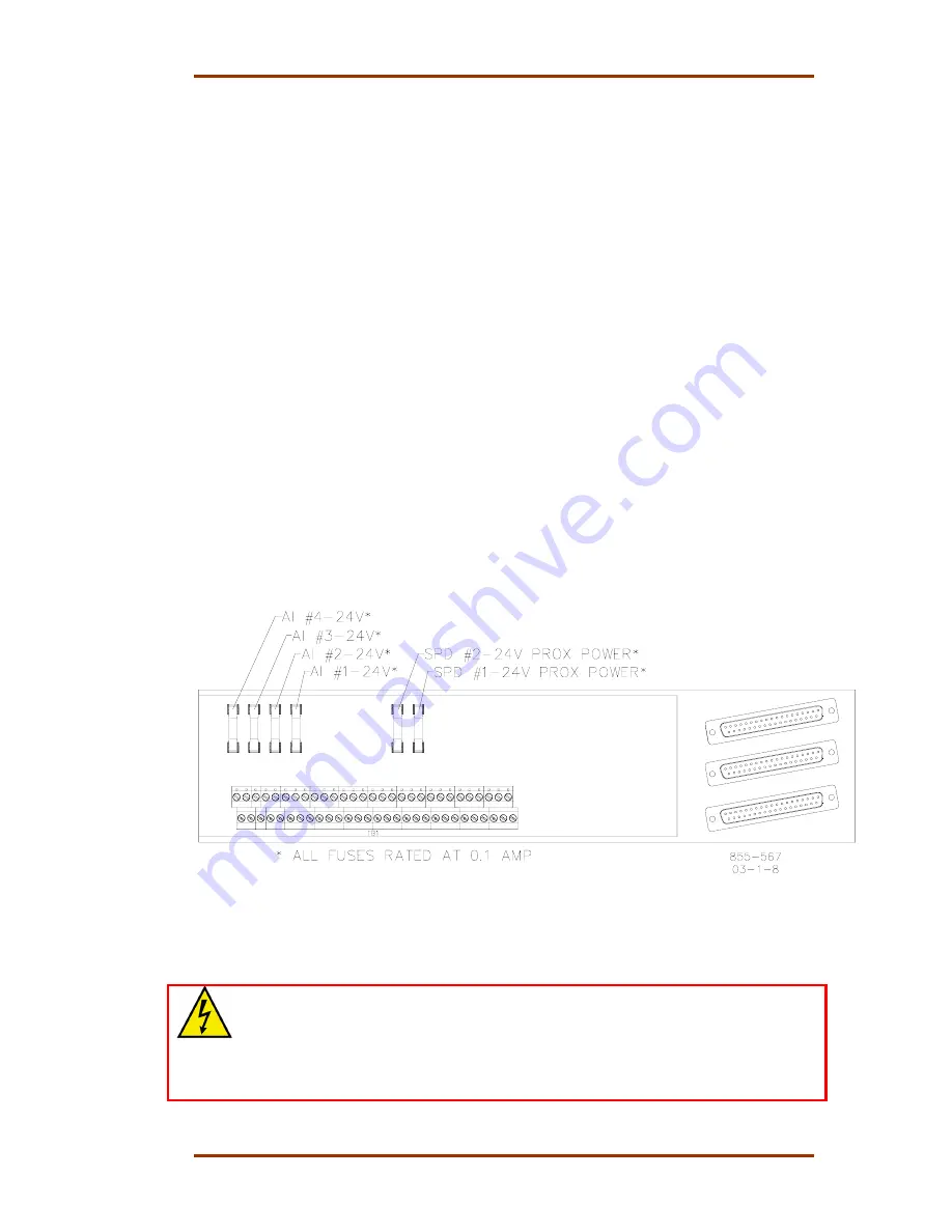
4. Locate and replace fuse (See Figure 5-1) with one of the same size and
rating (24 Vdc/0.1 A).
5. Replace ATM Cover.
Figure 5-1. ATM Fuse Locations
To replace DTM Relays:
WARNING—HIGH VOLTAGE
Relay circuit power is also present on a DTM’s relay and cable connectors.
When using high voltage relay circuit power, it is recommended that care be
taken not to touch exposed connectors when replacing relays or cables. If
possible remove relay circuit power from all DTM relays before replacing any
DTM relay or cable.
1. Read all warnings on pages v and vi of this Volume before replacing any
Relay.
Summary of Contents for MicroNet TMR 5009
Page 8: ...5009 Installation Hardware Manual 85580V2 vi Woodward...
Page 23: ...Manual 85580V2 5009 Installation Hardware Woodward 15 Figure 3 1 Hardware Identification...
Page 33: ...Manual 85580V2 5009 Installation Hardware Woodward 25 Figure 3 7 DIN Rail ATM Outline Drawing...
Page 35: ...Manual 85580V2 5009 Installation Hardware Woodward 27 Figure 3 9 DTM Outline Drawing...
Page 36: ...5009 Installation Hardware Manual 85580V2 28 Woodward Figure 3 10 DTM Mounting Configuration...
Page 68: ...5009 Installation Hardware Manual 85580V2 60 Woodward Figure 4 19 System Cable Layout Diagram...
Page 69: ...Manual 85580V2 5009 Installation Hardware Woodward 61 Figure 4 20 Power Supply Wiring Diagram...
Page 70: ...5009 Installation Hardware Manual 85580V2 62 Woodward Figure 4 21 ATM 1 Wiring Diagram...
Page 71: ...Manual 85580V2 5009 Installation Hardware Woodward 63 Figure 4 22 ATM 2 Wiring Diagram...
Page 72: ...5009 Installation Hardware Manual 85580V2 64 Woodward Figure 4 23 DTM 1 Wiring Diagram...
Page 73: ...Manual 85580V2 5009 Installation Hardware Woodward 65 Figure 4 24 DTM 2 Wiring Diagram...
Page 74: ...5009 Installation Hardware Manual 85580V2 66 Woodward Figure 4 25 DTM 3 Wiring Diagram...
Page 75: ...Manual 85580V2 5009 Installation Hardware Woodward 67 Figure 4 26 DTM 4 Wiring Diagram...
Page 89: ...Manual 85580V2 5009 Installation Hardware Woodward 81 Table 5 3 Discrete In Cable Connections...
Page 90: ...5009 Installation Hardware Manual 85580V2 82 Woodward Table 5 4 Relay Cable Connections...
Page 91: ...Manual 85580V2 5009 Installation Hardware Woodward 83 Table 5 4 Relay Cable Connections cont...
Page 92: ...5009 Installation Hardware Manual 85580V2 84 Woodward Table 5 5 Analog Combo Module...
Page 103: ...Manual 85580V2 5009 Installation Hardware Woodward 95 Figure 8 2 Operator Control Panel...
Page 108: ...5009 Installation Hardware Manual 85580V2 100 Woodward Figure 8 6 Real Power Sensor...
Page 115: ......
Page 116: ...Declarations...
Page 117: ......


