


Appendix A: Technical Drawings
ii. Rear Panel Connections (Desktop Model)
VT200/220 Technical Manual, Rev 1.00.01
80
Doc
#
TM-VT200/220-EN
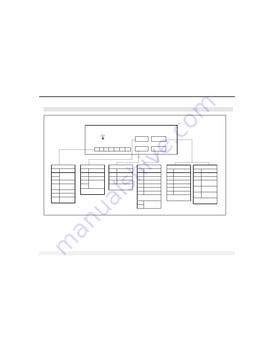
ii. Rear Panel Connections (Desktop Model)
1 2 3 4 5 6 7
+ - I
1
C
I
O
1
O
2
+
C
o
COM 1
Pin Description
2
RX or DTR
3
TX
5
GND
D-Type Metal Case
(Shield)
P
OWER
&
S
ETPOINTS
Pin Description
1
2
Power
9-15 VDC
3
Input 1
4
Input
Common (-)
5
Output 1
6
Output 2
7
Output
Common (+)
COM 2
Pin Description
6
A
7
B
8
9
Termination
resistor
(120R)
D-Type Metal Case
(Shield)
L
OAD
C
ELL
1
Pin Description
1
Excitation (-)
2
Sense (-)
3
Sense (+)
4
Excitation (+)
5
Signal (-)
6
Signal (+)
D-Type Metal Case
(Shield)
7
8
Calibration
Enable
COM 2
COM 1
Load Cell 2
or
Analog Output
Load Cell 1
DB9 fem
DB9 male
DB15
fem/male
DB15 fem
L
OAD
C
ELL
2
(DB15
F)
Pin Description
1
Excitation (-)
2
Sense (-)
3
Sense (+)
4
Excitation (+)
5
Signal (-)
6
Signal (+)
D-Type Metal Case
(Shield)
A
NALOG
O
UTPUT
Pin Description
1,9
IOut (+)
2,10
VOut (+)
3,11
IOut (-) or
VOut (-)
4,12
Power in
+24 VDC
5,13
Power in
GND
D-Type Metal Case
(Shield)
NOTE:
Short pins
8,9 for termination
resistor (120R)
connection