


Outputs and Digital Input
Connecting Digital Outputs and Tilt Switch
VT200/220 Technical Manual, Rev 1.00.01
65
Doc
#
TM-VT200/220-EN
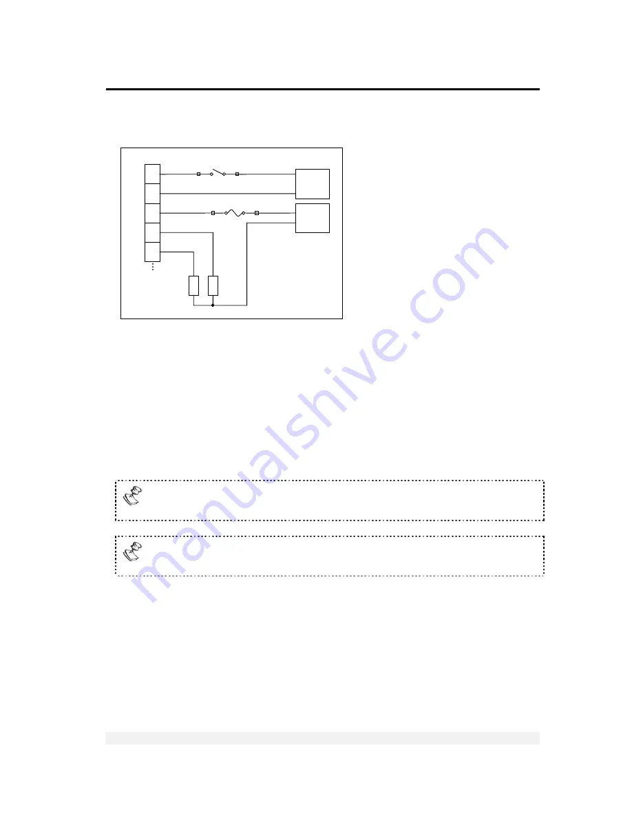
7.2 Connecting Digital Outputs and Tilt Switch
Figure 12 – Digital output and tilt switch connection diagram
7.3 Setting
Thresholds
for Digital Setpoints
Each setpoint has an upper weight threshold that triggers it. For example, if you set a
threshold of 13kg for setpoint 1, nothing will happen as long as the items on the scale
weigh less than 13kg. As soon as the weight measured reaches exactly 13kg, or
more, the setpoint will be switched on (if normally off) or off (if normally on).
You can use the two setpoints to set an upper and lower range for a production
operation. For example, if the weight of a product drops below the threshold for
setpoint 1, or goes above the threshold for setpoint 2, it can be rejected.
Setpoints can be activated either by net weight or by gross weight, depending
on setup parameter 5.6.
Setpoints can be either normally open or normally closed, depending on setup
parameter 5.7.
Power &
Setpoints
Connector
3
4
7
5
6
I
1
C
I
C
O
O
2
O
1
Input 1
Tilt Switch
Output 1
Output 2
Fuse
Digital
Outputs
Imax=100m
+
+
+
+
- -
-
-
L
O
A
D
L
O
A
D
Power
Supply
9-24VDC
Power
Supply
24VDC